Definition: A type of servomotor that uses DC electrical input to generate mechanical output like velocity, acceleration or position is known as DC servomotor. It is somewhat similar to a normal DC motor. However, there exist some differences between a normal dc motor and dc servomotor.
Basically, DC servomotors of all types are required to be excited individually. This leads to provide linear characteristics between torque and speed.
Introduction
We have already discussed in our previous article that servomotors are the devices that are used to change electrical input into positional mechanical output. A normal dc motor that utilizes the principle of servomechanism simply converted into a dc servomotor.
More simply, we can say that a DC motor controlled with servomechanism is known as DC servomotor.
It is known to us that the type of input applied to the servomotor leads to its classification as AC servomotor and DC servomotor.
So, in the case of DC servomotor, the applied dc input causes the motor to rotate and acquire the desired position at the specified angle. It is a closed-loop operation and uses position feedback to precisely adjust the position at the desired angle.
The DC servomotor is further classified on the basis of control provided to it. Basically, controlling to the DC servomotor is either provided from the field side or from the armature side. And this further classifies the DC servomotor.
Here in this article, we will discuss each type separately.
Field Controlled DC Servomotor
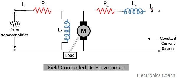
In this type of DC servomotor, the controlling is provided to the field winding. More specifically, we can say, the controlled signal received from the amplifier is fed to the field winding. Thus, it is named so.
While the armature current is maintained at a constant value using a constant current source.
The figure given below represents the field controlled DC servomotor:
It is to be noted here that the field in this type of dc servomotor can be either electromagnetic type where a salient pole is present with a field winding wound around it and excitation to it is provided with dc current or a permanent magnet type.
Basically, according to the general torque equation of DC motor, the torque is directly proportional to the product of field flux and the armature current. However, in this specific type, the armature current is kept constant thus,
T α Φ
We have already discussed the amplified error signal from the servoamplifier excites the field. And in this way, the excitation provided controls the torque i.e., the rotation of the motor.
In case the value of the current source applied at the armature is quite large, then for a small change in field current, there will be a proportional change in the torque of the motor.
It is to be noted here that the direction in which the shaft rotates can be changed according to the polarity of the field or the by using split field dc motor.
When the direction of rotation is polarity dependent then this signifies that with the change in polarity of the field, the rotational direction also changes.
However, sometimes by the use of split field dc motor, the rotational direction of the motor changes. This is so because as the name suggests in this type of motor, the winding is split into two parts, where one part is wounded in a clockwise direction while the other in an anticlockwise direction.
In this case, the error signal is provided at the junction of the winding. As the two windings possess a magnetic field in the opposite direction. Thus, when the error signal is provided then one side of the magnetic field will dominate the other. So, the motor rotates in the direction of the winding of the dominating side according to the error signal.
Here, the ratio of reactance to resistance is quite large thereby exhibiting the high value of the time constant. This implies that for quick changes in the control signals the response will be slower. Thus, is majorly used in small rated motors.
However, here the power requirement is less as the motor is controlled by the field.
Armature Controlled DC Servomotor
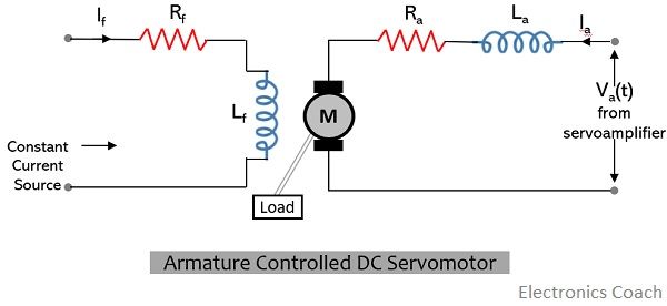
In armature controlled dc servomotor, the controlling is provided at the armature. This means, here the signal from the servoamplifier is provided at the armature and constant current is provided at the field winding.
The voltage from the servoamplifier, Va(t) with resistance Ra and inductance La is provided at the armature. And this input voltage at the armature controls the shaft.
The figure below represents the arrangement of armature coupled dc servomotor: Here the constant field is provided using the permanent magnets and hence no field coils are required.
In the field controlled dc servomotor, we have already discussed that torque is in direct proportion the field flux and the armature current. Thus, its operating principle is such that if the field flux is quite large then even with the small change in the armature current there will be a large change in torque. Thereby making the servomotor sensitive to armature current.
It is to be noted here that in armature controlled dc servomotor, the sensitivity towards the field current should be low. As the armature controlled motor must not respond to the field current.
It offers a small value of the time constant so there is a rapid change in the armature current of the motor with the change in the voltage applied at the armature. Thus, it provides a faster dynamic response where the direction of rotation changes with the change in polarity of the error signal.
Characteristics of DC Servomotor
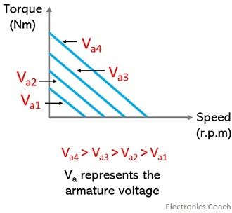
The figure below shows the torque-speed characteristics of armature controlled dc servomotor:
It is noteworthy here that, the above-shown characteristics are similar to the torque-speed characteristics of ac servomotor.
Leave a Reply