The Half Wave and Full Wave Rectifier have significant differences. A rectifier converts AC voltage into Pulsating DC voltage. A Half-Wave rectifier is an electronic circuit which converts only one-half of the AC cycle into pulsating DC. It utilizes only half of AC cycle for the conversion process. On the other hand, Full wave rectifier is an electronic circuit which converts entire cycle of AC into Pulsating DC.
The Half-Wave Rectifier is unidirectional; it means it will allow the conduction in one direction only. That’s why either it can convert positive half only or negative half only into DC voltage. This is the reason that it is called Half Wave Rectifier. While Full-wave Rectifier, is bi-directional, it conducts for positive half as well as negative half of the cycle. Thus, it is termed as full wave rectifier.
Content: Half Wave and Full Wave Rectifier
Comparison Chart
| Parameters | Half-Wave Rectifiers | Full-Wave Rectifiers |
|---|---|---|
| Rectification Efficiency | 40.6% | 81.2% |
| Ripple Factor | 1.21 | 0.482 |
| Transformer Utilization Factor | 0.286 | 0.692 |
| Voltage Regulation | Good | Better |
| Fundamental frequency of ripple | Equal to Supply Frequency, f | Double of Supply Frequency, 2f |
| Form Factor | 1.57 | 1.11 |
| Peak Factor | 2 | 1.414 |
| Number of diodes | Only 1 | Vary from 2 to 4, 4 in case of bridge rectifier |
| Peak Inverse Voltage | Vs | 2 Vs |
| DC Output Voltage | Imax/π RL | 2/π RL Imax |
Definition of Half Wave Rectifier
Half Wave Rectifier circuit consists of a single diode and a step-down transformer, the high voltage AC will be converted into low voltage AC with the help of step-down transformer. After this, a diode connected in the circuit will be forward biased for positive half of AC cycle and will be reversed biased during negative half.

When the diode is forward biased, it acts as a short circuit, while when it is reversed biased it acts as an open circuit. This is because of the connection architecture of the circuit. The P-terminal of the diode is connected with the secondary winding of transformer and N-terminal of the diode is connected with the load resistor.
Thus, the diode conducts during the positive half of AC cycle. While it will not conduct during the negative half of AC cycle. Thus, the voltage drop across the load resistor will appear only for the positive half of AC. During negative half of AC cycle, we will get zero DC voltage.
Definition of Full Wave Rectifier
Full Wave Rectifier consists of two diodes and one step down transformer which is centre tapped. The P-terminal of the diodes is connected to the secondary winding of the transformer. The N-terminals of both the diodes are connected to the centre tapping point of the secondary winding, and they are also connected to load terminal.
When positive half of AC cycle passes through transformer primary winding, then due to mutual induction the top of the secondary winding becomes positive while the bottom of the secondary winding becomes negative.
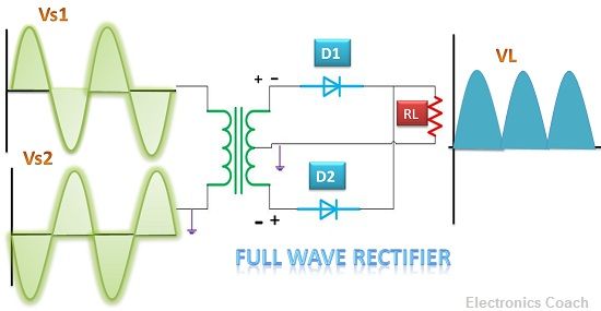
The P-terminal of diode D1 is connected to the positive voltage which makes the diode to operate in forward biased region. At the same time diode D2 becomes reverse biased, due to the negative voltage at the bottom of the secondary winding.
Thus, for the positive half cycle of AC, only diode D1 conducts, and diode D2 does not conduct.Thus, when the negative half cycle of AC passes through the primary winding of transformer then due to mutual induction the top of the secondary winding of transformer becomes negative and bottom of the secondary windings become positive.
Now, diode D2 will be forward biased, and diode D1 will be reverse biased. Thus, DC voltage will be obtained for positive half of AC cycle as well as for negative half of AC cycle. Thus, it is called full wave as it conducts for the full cycle of AC.
Key Differences Between Half Wave and Full Wave Rectifier
- The significant key difference between half wave and full wave rectifier is efficiency. Half wave rectifier is a low-efficiency rectifier while the full wave is a high-efficiency rectifier. Thus, it is always better to use full wave when we are working on the highly efficient application.
- The centre tapping also differs in half wave and full wave rectifier. Half wave rectifier does not require centre tapping of the secondary winding of transformer while full wave requires centre tapping of the secondary winding of the transformer.
- The requirement of components varies in Half Wave and Full Wave Rectifier. Full wave requires more electronic components as compared to half wave. Thus, full wave rectifier is costly as compared to half wave. Full wave requires double the number of diodes.
- The losses due to saturation of DC core in half wave and full wave rectifiers also create the significant difference. The half wave possesses DC saturation of core, but this problem can be overcome in the full wave circuit.
- The full wave circuitry does not possess DC saturation of transformer core because the current in the secondary winding flows in two halves of the secondary winding of the transformer and in opposite directions.
Conclusion
A rectifier is a crucial component in various electronic circuits. This is because most of the electronic circuits operate on low voltage DC and it is economical to supply power in the form of AC. Thus, we need a device which can convert AC to DC. A rectifier is a device which converts AC voltage into Pulsating DC voltage.
The pulsating DC voltage consists of AC ripples with DC voltage. Thus, it is called Pulsating DC voltage. The half wave rectifier converts half cycle of AC into pulsating DC while full wave converts full cycle into pulsating DC.
Our selection for half wave and full wave rectifier should be based upon the requirements. If we require a low-cost device and if you can compromise with efficiency then use half wave. But if you are working on some specific circuit designing which requires highly efficient conversion of AC to DC then use full wave, keeping in mind its circuit complexity and high cost.
Rachel says
Tq fr ur answer….👍
tauqeer ahmad says
good lecture
sophie says
well uderstood thank you
Dauda says
That’s very good I really love physics
Jithin Cheeramban says
Thanks for your notes
khan Gach says
Thanks