Definition: Peak detector circuits are used to determine the peak (maximum) value of an input signal. It stores the peak value of input voltages for infinite time duration until it comes to reset condition. The peak detector circuit utilizes its property of following the highest value of an input signal and storing it.
Rectifier circuits usually provide an output in proportion to the average value of the input. However, some application requires measurement of the peak value of the signal. Thus, peak detectors are used.
Usually, the peak of non-sinusoidal waveforms is measured using a peak detector. As traditional ac voltmeter cannot measure the peak of such signals.
Circuit Working of Peak detector
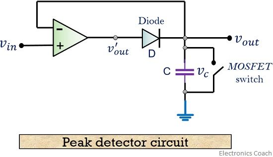
The figure below shows the circuit of a basic positive peak detector-

It consists of a diode and capacitor along with an op-amp as shown above. The circuit does not require any complex component in order to determine the peak of the input waveform.
Working Principle
The working principle of the circuit is such that, the peak of the input waveform is followed and stored in terms of voltage in the capacitor.
By the time on moving further, if the circuit detects a higher peak, the new peak value is stored in the capacitor until it is discharged.
The capacitor employed in the circuit is charged through the diode by the applied input signal. The small voltage drop across the diode is ignored and the capacitor is charged up to the highest peak of the applied input signal.
Let us consider initially the capacitor is charged to voltage Vc. The diode employed in the circuit gets forward biased when the applied input voltage Vin exceeds the capacitor voltage Vc. Thereby allowing the circuit to behave as a voltage follower. The output voltage follows the applied input voltage until Vin is more than Vc.
As the input voltage Vin reduces below the value of capacitive voltage Vc, it causes the diode to get reverse biased. In such condition, the capacitor retains the value until the input again exceeds the value stored in the capacitor.
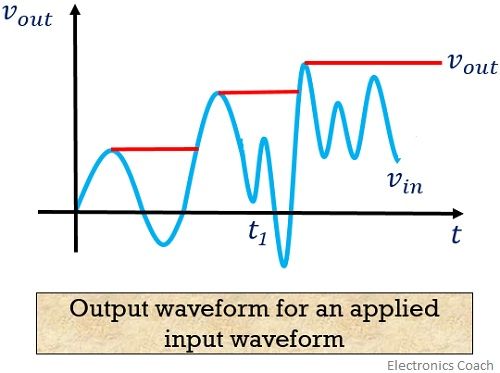
The figure below shows the output voltage waveform for an applied input signal.

As we can see in the waveform shown above, at time t1, the circuit misses the peak of the input signal as it is less than the previous peak of the input signal. Thereby allowing the capacitor to hold the value of the previously occurred peak.
As it is a positive peak detector, one can also construct a negative peak detector circuit, that will hold the lowest or most negative signal voltage. This is basically done by reversing the polarities of the diode in the circuit.
Improvement in peak detector circuit
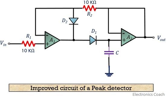
The figure below shows the circuit of an improved peak detector. It is used to buffer the source of the signal from that of the capacitor.

As we can see the circuit is comprised of 2 Op-amps. However, the basic circuit of the peak detector contains only one Op-amp. A high impedance load is offered by the op-amp A1 to the source. While op-amp A2 performs buffering action in between the load and capacitor.
The same basic principle is applied in this circuit also. The voltage at the output side is the similar as the peak of the input signal stored in the capacitor.
Its working is such that, as the input voltage becomes higher than the charge stored on the capacitor, it charges itself with the new higher value of input signal.
However, for a smaller value of the input, the capacitor sticks to the previous higher value. The diode D2 employed here restricts the output of op-amp A1 from reaching negative saturation.
This basically provides an improvement in the recovery time of op-amp A1 at the condition of attaining a higher peak than the previous. The two resistances serve as the path for the bias current of input to A1.
To prevent the effect of the offset voltage, the value of the two resistances R1 and R2 are kept equal.
The necessary frequency compensation must be given to op-amp A1 in order to have stability against oscillations.
Applications of Peak detector
- It is used in the analysis of spectral and mass spectrometer.
- Peak detector finds its application in destructive testing.
- It is used for instrumentation measurement, mostly in amplitude modulated wave communication.
- It widely finds applications in sound measuring instruments.
From the above discussion, we can conclude that peak detectors are used to overcome the disadvantage of ac voltmeter. As the peak of a square, sawtooth or any random waveform is not measured using ac voltmeter.
Irfan Nadaf says
Good
JOSHNA says
VERY NICE