Definition: The circuits that are composed of semiconductor material and are designed to change constant alternating voltage directly to variable alternating voltage keeping the frequency unchanged. So, the frequency of the fixed as well as variable ac voltage will remain the same. It is sometimes also known as AC Regulators.
These are basically phase-controlled devices, line commutated thyristors or triacs are used thus, the need for a complex commutation circuit does not exists here.
Introduction
AC voltage controllers are regarded as thyristor power converters that transform constant voltage, ac input supply of fixed frequency into variable voltage ac output of the same frequency. It simply varies the RMS value of alternating voltage provided to the load circuit.
Majorly its applications include heating (either for domestic or industrial purposes), lighting control, speed controlling of ac drives, starting of induction motor, transformer tap changing, etc. The ac voltage controllers constituted by thyristors or triacs are highly efficient and are flexible, small-sized and requires less maintenance. These can also operate in conjunction with closed-loop control systems. By varying the firing angle α, the power that flows through the load as well as the output voltage both can be controlled.
There are basically, two types of control strategies in order to regulate the power flow are mentioned:
- Phase Control
- Integral Cycle Control
Single-Phase AC Voltage Controllers
The figure here shows the circuit representation of a single-phase ac voltage controller: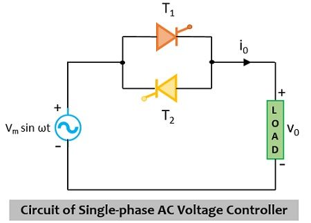
Here it is clearly shown that two thyristors are present in the circuit that exist in the antiparallel arrangement. It is to be kept in mind that the sources through which triggering to the thyristors is provided must be isolated from each other.
If we consider a single-phase full-wave voltage controller then it should contain 2 thyristors along with two diodes. In such case, during the first half of the ac signal, only a single thyristor and a diode will be in the conducting state while in the second half of the ac signal, the other thyristor and diode will offer conduction. There is a disadvantageous factor associated with this circuit which is that there will be more conduction losses thereby resultantly causing a reduction in the efficiency of the circuit.
It is known to us that AC to AC voltage converters work on AC supply sources so that the output voltage can be regulated.
The figure below shows a single-phase voltage controller that feeds power to the resistive load R:
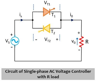
The input supply source to the circuit is Vs and the gating pulses are ig1 and ig2, the source current is is, load current and load voltage i0 and v0 respectively. The voltage across the two thyristors in the circuit will be vT1 and vT2 respectively.
The circuit operation takes place in a way that initially during the positive half of the supply input, T1 comes in a forward biased state and the triggering pulse is provided at firing angle α. Once T1 is forward biased then it comes to the conducting state and the source voltage is given in the duration from the firing angle α to π. At the instant π, the load current and load voltage i0 and v0 attain zero value. However, after passing through π, the potential across T1 will lead to switch its state from forward bias to reverse bias and this turns off the thyristor.
When negative half of the ac input is supplied, triggering to T2 is provided at (π+α). Once the triggering pulse is provided then T2 begins to conduct from π+α to 2π. However, once 2π is reached then the thyristor T2 is provided with reverse biased potential and hence reaches commutation. In this duration, the waveform representation for i0 and is will be the same.
In the duration between 0 to α, i.e., in the forward-biased state of T1 the voltage across the thyristor will be equivalent to the source voltage, meaning vT1 = Vs. Thus, in the conducting state, the voltage across T1 will be around 1V. While as we have discussed that after instant π, T1 will get reverse biased. By this time, T2 begins to conduct, for the duration π+α to 2π. Basically, T1 will get reverse biased because of the voltage drop across T2 which is nearly around 1 to 1.5 V.
In the waveform representation shown below, one can easily analyze the voltage drop across the two thyristors.
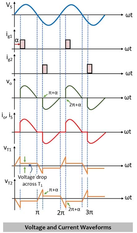
From the above representation we can conclude that whatever the value of α is, the duration up to which each individual thyristor will be reverse biased will be π/ω sec.
Thus, we can say, in the two-thyristor topology, out of the two thyristors, one will be forward biased in each half of the supply input. The power which is delivered to the load is decided by the RMS voltage Vrms:
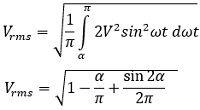
In this case, significant harmonics get introduced in the load as well as supply. Due to this reason, these controllers do not find uses in recent times.
Multistage Sequence Control of Voltage Controllers
Multistage sequence control of ac voltage controllers is used to have less value of harmonic content in comparison to two-stage sequence control. The figure shown here represents the n-stage sequence control of voltage controllers:
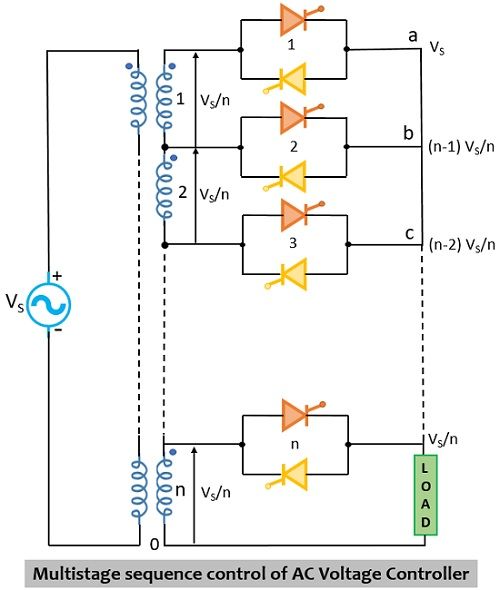
Here the transformer has n secondary windings and each winding is rated vs/n where vs corresponds to the source voltage. The harmonics in output voltage relies on the magnitude of variation in the voltage. The dependency is such that when the variation in voltage is small in comparison to the total output voltage then there will be less harmonic content present in the output voltage.
Leave a Reply