Definition: A technique by which analog signal gets converted into digital form in order to have signal transmission through a digital network is known as Pulse Code Modulation. It is abbreviated as PCM.
PCM systems are basically signal coders also known as waveform coders. PCM allows the representation of the continuous time message signal as a sequence of binary coded pulses. The binary form permits only 2 probable states i.e., 0 and 1.
The major steps involved in PCM is sampling, quantizing and encoding which will be discussed in detail in the upcoming sections.
Basics of PCM
In pulse code modulation, the analog message signal is first sampled, and then the amplitude of the sample is approximated to the nearest set of quantization level. This allows the representation of time and amplitude in a discrete manner. Thereby, generating a discrete signal.
This discrete signal is then converted into its binary form for the transmission of the signal.
It is to be noted here that, in PCM technique the signal gets transmitted in the coded format and must be decoded at the receiver in order to have the original message signal.
Block diagram of Pulse Code Modulation
The figure below shows the block diagram representing a PCM system
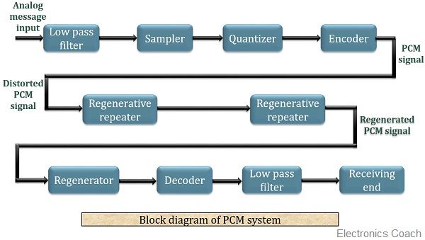
It is basically composed of a transmitter, a transmission path and a receiver. The transmitter performs the sampling, quantizing and encoding of the signal. The transmission path includes regenerative receivers that recover the signal from the undesired noise effects.
Lastly, the receiver section that performs decoding of the coded signal after regeneration of the signal at the receiver. Let us now understand the working of each section in detail:
PCM Transmitter
The detailed diagram of a practical PCM transmitter is shown below
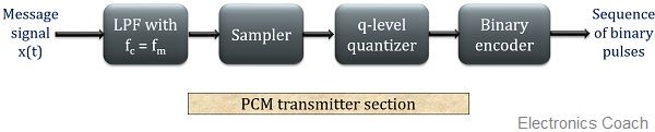
- LPF: Here, the message signal which is in the continuous time form, is allowed to pass through a low pass filter (LPF). This LPF whose cutoff frequency is fm eliminates the high-frequency components of the signal and passes only the frequency components that lie below fm.
- Sampler: The output of the LPF is then fed to a sampler where the analog input signal is sampled at regular intervals. The sampling of the signal is done at the rate of fs. This sampling frequency is so selected that it must follow the sampling theorem that is expressed as:
fs ≥ 2fm
The output of the sampler is a signal that is discrete time continuous amplitude signal denoted as nTs which is nothing but a PAM signal.
- Quantizer: A quantizer is a unit that rounds off each sample to the nearest discrete level. The sampler provides a continuous range signal and hence still an analog one. The quantizer performs the approximation of each sample thus assigning it a particular discrete level.
As it basically rounds off the value to a certain level this shows some variation by the actual amount. Thus we can say, quantizing a signal introduces some distortion or noise into it. This is known as quantization error.
This noise factor is somewhat better than the channel noise as it is controllable.
A quantizer can be of two types, uniform and non-uniform quantizer. In uniform quantizer, there exists a uniform spacing in between the level. As against, in non-uniform quantizer, the spacing in between the levels is not uniform. Here, we have employed a uniform quantizer.
For a low signal level, the quantization error is high i.e., bad SNR. But, for a high signal level, the quantization error is low providing good SNR.
The figure below shows the sampling of analog signal and further quantization of the samples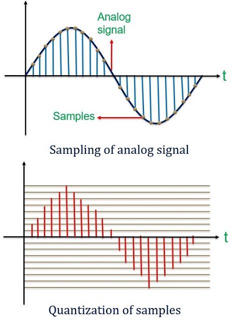
- Encoder: An encoder performs the conversion of the quantized signal into binary codes. This unit generates a digitally encoded signal which is a sequence of binary pulses that acts as the modulated output.
As it is a binary encoder thus generates a binary coded sequence. That is transmitted through the transmission path.
Transmission path in a PCM system
A PCM system has a better control over signal distortion introduced during transmission through the channel than other systems. PCM achieves low signal distortion by employing regenerative receivers along the transmission path.
The channel introduces distortion in the signal during transmission. This distortion is eliminated by the regenerator in order to provide a distortionless PCM signal. Resultantly, enhancing the transmission ability of the system.
The figure below shows the block diagram of a regenerative repeater. It basically performs equalization and timing and then executes decision making.
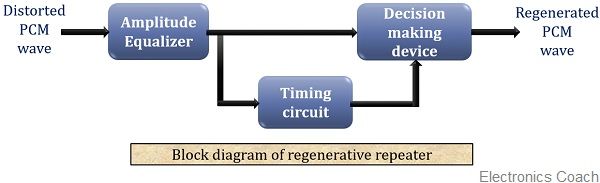
The PCM signal when provided to the regenerative repeater, the equalizer circuit at the beginning performs the reshaping of the distorted signal. At the same time, the timing circuit generates a pulse train that is a derivative of input PCM pulses.
This pulse train is then utilized by the decision-making device in order to sample the PCM pulses. This sampling is done at the instant where maximum SNR can be achieved. In this way, the decision-making device generates the distortionless PCM wave.
PCM Receiver
The figure below shows the functional block diagram of a PCM receiver
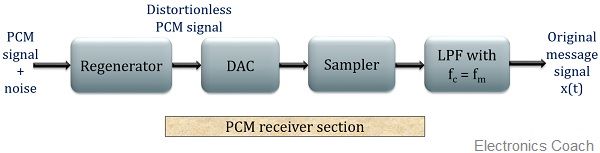
- Regenerator: A regenerative repeater is placed at the receiving end also so as to have an exact PCM transmitted signal. Here, also the regenerator works in a similar manner as that when employed in the transmission path. It eliminates the channel induced noise and reshapes the pulse.
- DAC and Sampler: Digital to analog converter performs the conversion of digital signal again into its analog form by making use of the sampler. As the actual message signal was analog thus at the receiver end there is a necessity to again convert it into its original form.
- LPF: The sampler generates analog signal but that is not the original message signal. Thus, the output of the sampler is fed to the LPF having cutoff frequency fm. This is sometimes termed as the reconstruction filter that produces the original message signal.
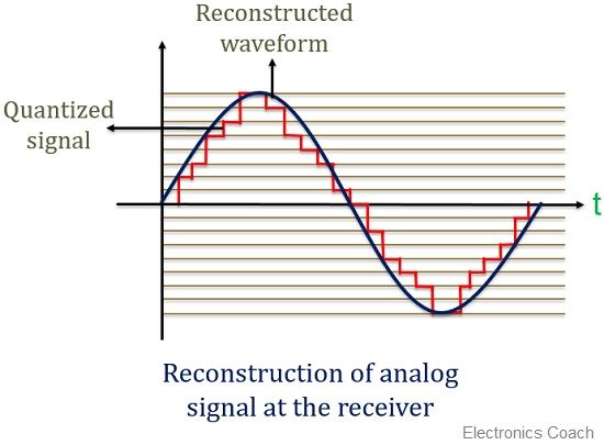
The process done at the transmitter is somewhat reversed at the receiver in order to generate the original analog message signal. The figure below shows the reconstruction of the actual analog message signal at the receiver.
Transmission bandwidth in Pulse Code Modulation
The transmission bandwidth of a PCM system is associated with a number of bits per sample. If the number of bits per sample increases, the bandwidth also increases. In order to have a good approximation, a large number of levels must be used but that will lead to a larger bandwidth requirement.
Let us consider each quantizer level is represented by ‘n’ binary digits. Then the levels represented by n binary digits is given as,
q = 2n
: q is the digital level of the quantizer
Every sample is changed into n bits, thus, a number of bit per sample is ‘n’.
As we have already discussed the number of samples per second is fs. Hence the number of bits per second which is also termed as signalling rate is given as,
r = n fs
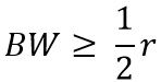
As transmission bandwidth is half the signalling rate, hence
As we have already discussed, r = nfs
Therefore,
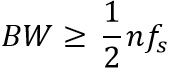
But we know, fs ≥ 2fm
Thus the bandwidth of the PCM system is given as,
BW ≥ n fm
Advantages of PCM
- Immune to channel induced noise and distortion.
- Repeaters can be employed along the transmitting channel.
- Encoders allow secured data transmission.
- It ensures uniform transmission quality.
Disadvantages of PCM
- Pulse code modulation increases the transmission bandwidth.
- A PCM system is somewhat more complex than another system.
Thus from the above discussion, we can conclude that a PCM system, transmits data in a coded format, that ensures secured transmission. But, this at the same time needs decoding system in order to reproduce exact message signal that increases system complexity.
Leave a Reply