Definition: Static Circuit Breakers are circuits that are composed of semiconductor materials and are designed to break the continuously flowing current through a circuit. The interruption offered here exhibit quickness and reliability.
More simply, it is a mechanical switching device that carries and interrupts current in case of normal circuit conditions along with some specified abnormal circuit conditions like a short circuit. Mainly static circuit breakers are classified into two categories, namely,
- Static AC Circuit Breakers
- Static DC Circuit Breakers
Introduction
The circuit breakers are known to be devices that exhibit switching capability and are used for the protection of electrical power systems. One of the major reasons for the incorporation of circuit breakers in electrical circuits is that circuits that are present in modern power systems are subjected to handle large currents. Such high currents may cause electrical faults in the system whenever malfunctioning occurs. Thus, safe interruption of the excessively flowing current through the circuit is required and for this purpose, specially designed circuit breakers are used.
Let us now proceed to understand the circuit operation of each type of circuit breaker.
Static AC Circuit Breakers
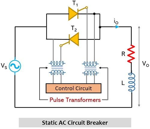
The operation of the static ac switch is similar to that of the static ac circuit breaker. Here we have shown the circuit representation of static ac circuit breaker:

It is known to us that when supply input is provided to the circuit along with the triggering pulse then the two thyristors in the circuit come into action and the current begins to flow through them. Now, as we have discussed that the aim of the circuit breaker is to break or interrupt the flow of current. Thus, here in order to break the circuit, the triggering pulse which was given to start the conduction is withdrawn.
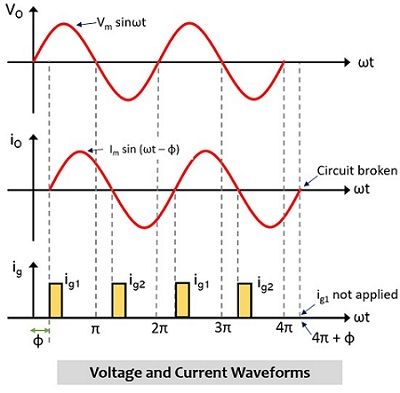
The current and voltage waveforms for the respective circuit is shown below:

Here suppose at 4π + φ, if gate pulse i.e., ig1 is not provided to thyristor T1, then it will not get on and at this instant T2 is already, it is due to this reason, the conduction stops as circuit continuity gets halted at this instant. Thus, whenever, there is any system fault then a turn-off command is provided and instantly the triggering pulse from T1 or T2 is removed and this leads to the breaking of the circuit.
Consider the waveform shown above and assume that the system sends the turn-off command to the circuit at instant 3π + φ, then the load current will take a specific amount of time to stop flowing through the circuit and it will be around 4π + φ when the circuit current will break. This means that there will be a delay of a complete or a half cycle for the turnoff to take place. Even if the turn-off command is received by the circuit between 3π + φ to 4π + φ then also circuit will get turned off at 4π + φ.
Hence the time delay for the circuit to get turned off after getting the command is around one half-cycle i.e., π/ω seconds after the turn-off command is received. The reason for the same is that during operation the circuit will be performing some necessary operations when turn-off command is received thus this leads to the introduction of turn-off delay.
Static DC Circuit Breakers
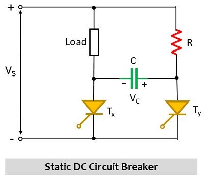
The figure shown here represents the circuit arrangement of static dc circuit breaker:

One can clearly see that this circuit arrangement is resembling with the circuit used for class-C commutation. We have already discussed in our previous contents that whenever the supply input provided to the circuit is of dc nature then in order to turn the thyristor off forced commutation will be required.
So, when Tx is turned on then the supply voltage will appear at the load thus the voltage across the load will be Vs. Due to the flow of current, the capacitor C in the circuit starts charging through the path Vs – R – C – Tx. The charge across the right-side plate of the capacitor is positive. Now, to have forced commutation, the thyristor Ty in the circuit i.e., the auxiliary thyristor is turned on.
Due to the polarity of the voltage Vc existing across the capacitor, the thyristor Tx will get reverse biased and will get turned off. Hence, in this way Tx i.e., the main thyristor will be under forced commutation. At the same time, due to the existing polarity of the capacitor, the thyristor Ty will come in a forward-biased state and begins to conduct. The direction of flow of current will be from Vs – load – C – Ty. Now, due to this flow of current, the polarity across the capacitor will get reversed and now the left-hand plate will hold the positive charge once the capacitor gets fully charged.
At this time, the load current will become zero and simultaneously the current flowing through the resistor R will become less than the holding current of the auxiliary thyristor. This leads to turning off of the thyristor Ty naturally.
Leave a Reply