The major factor that differentiates multiplexer and demultiplexer is their ability to accept multiple input and single input respectively. The multiplexer also known as a MUX operates on several inputs but provide a single output. As against demultiplexer also known as DEMUX simply reverses the operation of MUX and operates on single input but transmits the data to multiple outputs.
It is noteworthy here that multiplexer acts as data selector thus provide a single output from several inputs. However, demultiplexer acts as a data distributor and generates several outputs with a single input.
We will discuss some other major differences between MUX and DEMUX but before that have a look towards the contents to be discussed under this article.
Content: Multiplexer vs Demultiplexer
Comparison chart
| Parameter | Multiplexer | Demultiplexer |
|---|---|---|
| Definition | A multiplexer is a combinational circuit that provides single output but accepts multiple data inputs. | A demultiplexer is a combinational circuit that takes single input but that input can be directed through multiple outputs. |
| Symbol | 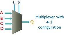 | 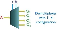 |
| Number of data inputs | Multiple | Single |
| Number of data output | Single | Multiple |
| Conversion technique | It performs parallel to serial conversion. | It performs serial to parallel conversion. |
| Device configuration | It is N to 1 device and thus behaves as data selector. | It is 1 to N device and thus behaves as data distributor. |
Definition of Multiplexer
It is a logic circuit that allows a single output to get generated by accepting multiple data input. Multiplexer consists of the control signal or data select input that concludes the output from several inputs. Thus, also known as the data selector.
It is referred to as many to one circuit due to its ability to select the single output from multiple inputs.
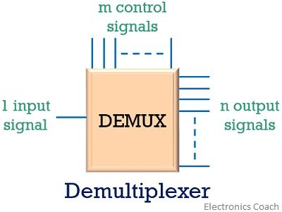
The figure below shows the circuit of a MUX including input, output and control signals.
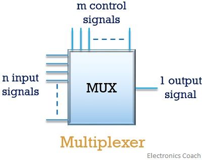
It works as a multi-position switch which is digitally controlled by the control signals. Here, the select lines determine which input will get switched to output among several inputs. As we can see in the figure shown above that n input signal is fed to a MUX, containing m control signals. However, only 1 data source is transmitted to output.
A relation exists between the input and select lines which is noteworthy and is given by:
2m = n
: m is the select lines and n is the input lines
One can have several configurations of multiplexer depending on input lines and the control signal applied to it.
Let us have a look at 4 to 1 multiplexer that consists of 4 input signal along with 2 control signals, in order to provide a single output.
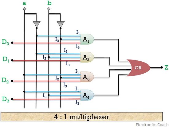
Here, 4 input bits applied to the MUX are D0, D1, D2, D3 and the control signals are a and b. So, any data input can be transmitted to output on changing the level of the control signal.
The truth table for the multiplexer is shown below. Let us consider 4 separate cases in order to understand the variation in output by controlling the level of control signals.
| Data select lines | Input selected | Input | Output | |
|---|---|---|---|---|
| a | b | D | D | Z |
| 0 | 0 | D0 | 0 1 | 0 1 |
| 0 | 1 | D1 | 0 1 | 0 1 |
| 1 | 0 | D2 | 0 1 | 0 1 |
| 1 | 1 | D3 | 0 1 | 0 1 |
Case 1: Consider that both the applied control signals a and b are low i.e., 0. In such a condition due to the presence of NOT gate inputs I1 and I2 of only AND gate 1 is high. So, if the input bit of D0 is high then the output is high and if the input of D0 is low then AND gate generates its output as 0.
Thus, with control signal level 00 only A1 is enabled and all others get disable hence output achieved is the reflection of data bit associated with A1.
Case 2: When control signal a is low and b is high then it causes AND gate 2 to be enabled as I1 and I2 of A2 will be high. So, input bit D1 decides the output of A2. If D1 is high, the output will be 1 otherwise 0.
Case 3: Now consider that level of control signal a is high and that of b is low. This enables only AND gate 3 as inputs I1 and I2 of A3 is high in this condition. So, applied input bit D2 will provide the desired bit at the output.
Case 4: Let us now consider the case when the level of both the applied control signals is high or 1. Then due to this only gate, A4 gets enabled while all others get disabled. Due to this, the output will be the result of applied input D3.
Definition of Demultiplexer
Demultiplexer basically reverses the operation of a multiplexer. It switches a single input to several outputs.
Here also control signal plays a major role by deciding the output to which the input is to be passed. It is also known as data distributor as it allows a single input to be distributed among multiple outputs.
Let’s have a look at the DEMUX configuration shown below that have only one input but m control and n output lines.
Moving further have a look at 1:4 demultiplexer consisting of data bit D, with 2 control signals a and b. Here, Z0, Z1, Z2, Z3 are the 4 output provided by the demultiplexer.
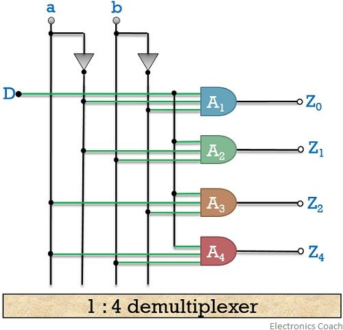
As we have already explained that for a particular value of control signal only a single AND gate is enabled while all others get disabled.
The truth table for a 1:4 DEMUX is shown below
| a | b | D | Z0 | Z1 | Z2 | Z3 |
|---|---|---|---|---|---|---|
| 0 | 0 | 0 | 0 | 0 | 0 | 0 |
| 0 | 0 | 1 | 1 | 0 | 0 | 0 |
| 0 | 1 | 0 | 0 | 0 | 0 | 0 |
| 0 | 1 | 1 | 0 | 1 | 0 | 0 |
| 1 | 0 | 0 | 0 | 0 | 0 | 0 |
| 1 | 0 | 1 | 0 | 0 | 1 | 0 |
| 1 | 1 | 0 | 0 | 0 | 0 | 0 |
| 1 | 1 | 1 | 0 | 0 | 0 | 1 |
Demultiplexer circuit also plays a major role in the communication system as sometimes parallel data reception is required. Thus, for such applications, these circuits are used.
Key Differences Multiplexer and Demultiplexer
- Both Multiplexers and Demultiplexers are combinational logic circuits used in communication system but their operation is exactly reverse of each other as one operates on multiple inputs and other on a single input.
- When we talk about data conversion technique then it is not difficult to understand that MUX performs parallel to serial conversion as it requires several inputs. However, DEMUX on a reverse note performs serial to parallel conversion as multiple outputs are achieved in its case.
- Multiplexer with the help of control signals selects the particular input that has to be transmitted at the output. On the contrary, Demultiplexer utilizes the control signal and allows us to have multiple outputs.
- Another key difference exists for MUX and DEMUX is that multiplexer is N to 1 device but demultiplexer is 1 to N device.
Conclusion
A communication system requires both multiplexer and demultiplexer due to its bidirectional nature but the operation of the two are exactly opposite to each other. The presence of control signals plays a crucial role in the working of MUX and DEMUX.
Leave a Reply