Definition: DC Drives are the functional circuitry designed to regulate the speed of the dc motor by offering precise controlling to the same. For a dc drive control system, it is said that it facilitates starting, stopping along with changing the direction and speed of the motor.
The major applications associated with dc motors are in adjustable-speed drives and position control applications. The speed controlling techniques for dc motors are quite simple and inexpensive in comparison to that of ac motors and because of this reason the fields where a wide range of speed controlling is required, dc drives are used.
Introduction
For the dc motors, it is said that these offer variable characteristics and are used in variable-speed drives. Due to its ability to provide high starting torque, speed control over a wide range can be achieved. Before proceeding further, let us first understand-
Electric Drives are the systems that perform the controlling action of electrical machines. It is mainly responsible for controlling the rotation of the shaft of the motor. It contains an electric motor, an energy transmitting device along with a working machine. The electric motor supplies the working power to the system so that the motor can rotate.
DC motors are an important part of various industrial drives. There are dc series motors that are formed when dc motors are used along with power electronic converters. There exists a classification of dc drives depending on the type of source provided or the method of voltage control. The classifications are as follows:
- Single-phase dc drives
- Three-phase dc drives
- Chopper drives
Let us understand each one separately.
Single-Phase DC Drives
The circuit arrangement for single-phase dc drives is shown below:
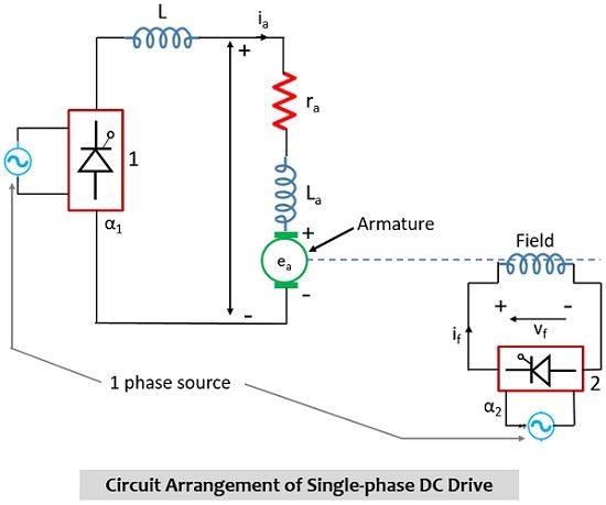
When we deal with phase-controlled dc drives, we use an ac to dc phase-controlled converter in order to control the dc drive motor. The controlled rectifier for dc-drives finds applications where there is a need for a wide range of speed controlling, as well as frequent starting, braking, and reversing. Some of the applications include a printing press, rolling mills, mine winders, machine tools, etc.
The firing angle control of converter 1 is regulating the voltage which is provided to the dc motor armature. Due to this reason, when α1 is varied then speed is controlled below base speed while α2 is varied then the field circuit provides speeds above the base speed. When α1 is of low value then armature current will exhibit discontinuity. When the armature current becomes discontinuous then there are chances of more losses in the armature and there will be poor speed regulation.
In order to deal with the discontinuity possessed by armature current, an inductor L is placed in series with the armature circuit so that ripples can be reduced. This makes the current continuous for lower motor speeds.
Three-Phase DC Drives
For high power applications (i.e., megawatts power) three-phase drives are used. The large dc drives are powered through three-phase controlled rectifiers. This provides fewer output ripples in comparison to single-phase drives thus ripple frequency is high with less filtering requirement. Unlike a single-phase drive that was providing discontinuous armature current, in a three-phase drive, the armature current is of continuous nature. This leads to providing better motor performance.
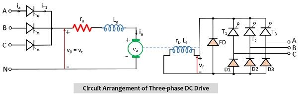
It is known that to control the speed of large motor drives three-phase converters are used. A three-phase controlled converter excites the armature circuit so as to get speeds below the base speed. But in order to get speed above base speed, another three-phase controlled converter is inserted in the field circuit.
Three-phase converters provide a higher output voltage in comparison to single-phase converters. Due to this reason, the inductance of lower value is required in a three-phase dc drive in comparison to a single-phase dc drive in order to reduce the armature current ripple.
Chopper Drives
Choppers are used in speed controlling of dc motor. Generally, when dc supply is given to the system then in that case speed of the motor is controlled by the chopper. There are several advantages like high efficiency, controlling flexibility, lightweight, small size, fast response.
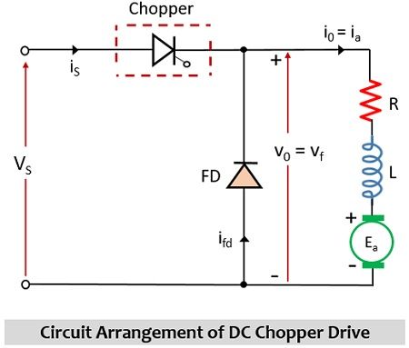
When fixed dc voltage gives rise to variable dc voltage then dc chopper is ideally used. When the speed of the dc motor armature is to be controlled below base speed then the chopper is placed between the dc source of fixed voltage and armature. This helps in regenerative braking of dc motor and the kinetic energy of the drive can be fed back to the source. Hence, energy can be saved to large extent and can be used in battery-operated vehicles where saving energy is quite an important factor.
In the case of dc chopper drives, the high-frequency output ripple voltage can be obtained by the use of a rectifier with a high pulse number. When a rectifier with a high pulse number is used then this provides a low utility factor for thyristors and this somewhat increases the cost.
Leave a Reply