The major difference between clipper and clamper is that clipper is a limiting circuit which limits the output voltage while clamper is a circuit which shifts the DC level of output voltage. The clipper and clamper circuits are exactly opposite to each other regarding their working principle.
Another significant difference between clipper and clamper is the shape of the output waveform. The voltage which is clipped by clipper can assume various shapes, but the voltage obtained by clamper circuit does not alter in shape.
Clipper is crucial when we want to modify the amplitude of the voltage. Clipping of signal amplitude is required in some application in which components cannot withstand the high magnitude of the voltage. While clamper is used when we need multiples of the input voltage at the output terminal.
We will discuss some more differences in the comparison chart.
Content: Clipper and Clamper
Comparison Chart
| Parameters | Clipper | Clamper |
|---|---|---|
| Defintion | Clipper delimit the amplitude of the output voltage. | Clamper shifts the DC level of the output voltage. |
| Output Voltage | Less than the input voltage. | Multiples of input voltage. |
| Energy storage component | Not required | Requires (Capacitor is used as energy storage element) |
| Shape of Output Waveform | Shape changes (Rectangular, sinusoidal, triangular etc.) | Shape remains same as input waveform. |
| DC Level | Remains same | DC level get shifted |
| Applications | In transmitters, receivers, amplitude selector, noise limiter etc. | In voltage multiplying circuits, Sonar, Radar system etc. |
Definition
Clipper
Clipper circuit is used to limit the amplitude of the input signal by clipping that part without affecting the remaining signal. It is desirable in some applications of electronics that excessive voltage should not pass through the components as they may get demolished. Thus, a particular value is obtained by reducing the amplitude of the signal using clipper circuit.
Effective of Positive Half of AC Cycle
The clipper circuit consists of a resistor, a diode and an AC source. When the positive half of AC cycle is introduced in the clipper circuit, the diode D1 becomes forward biased. Due to this the voltage obtained across the load will be same as the voltage across the diode.
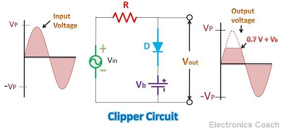
Please remember that if you are using Silicon diode, the voltage drop across it will be 0.7 V while if you are using Germanium diode the voltage drop across it will be 0.3 V approximately. Thus, the output voltage during the positive half of AC cycle will be equal to the voltage drop across the diode.
Now you must have got the idea that how clipper works. It is evident from the above diagram that the peak voltage (Vp) of input voltage was more, but the voltage obtained at the output is clipped.
In the above diagram, we have also used a battery in series with the diode. In this condition, the output voltage during the positive half of AC will be the sum of the voltage drop across the diode and the voltage of the battery connected in series with the diode.
Effective of Negative Half of AC
When the negative half cycle of AC strikes the circuit, then the diode D1 will become reversed biased, and no conduction will take place through it as it will be like an open circuit. It is clear from the above diagram that during the negative half of AC, the output voltage will be exactly same as the input voltage.
This was the example of positive clipper as we have clipped some part of positive half of AC. We can constitute negative clipper by reversing the diode and battery. We can also remove the battery but then the output voltage clipped will be according to the voltage drop across the diode only. Thus, to customize it according to our requirement we can use the battery. The battery voltage should be equal to the voltage which we require at the output.
Clamper
Clamper does not clip the input signal, but it shifts the DC level either upward or downward depending upon whether it is positive clamper or negative clamper.
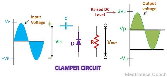
It consists of a capacitor, a diode, resistor and input AC source. When the negative half cycle enters clamping circuit, the diode becomes forward biased, and the capacitor starts charging. It charges till it acquires its peak value.
When the positive half of AC is introduced in the circuit, the diode becomes reverse biased and becomes an open circuit. In this condition, the capacitor starts discharging, and the complete AC input voltage appears across the load resistor. Thus, the output voltage in this condition will be equal to the sum of the input voltage and voltage across the capacitor.
The output voltage becomes two times of input AC voltage. Thus, from Vp (peak voltage), it gets shifted towards 2Vp. This circuit works like voltage multipliers. We can also design negative clampers by reversing the diode. In that case, the output signal will shift downwards.
Key Differences Between Clipper and Clamper
- The main difference between clipper and clamper is their function; clipper limits the voltage while clamper shifts in upwards or downwards.
- The usage of energy storing element also creates a key difference between Clipper and Clamper, Clipper does not require capacitor while clamper circuit cannot be completed without energy storing element, i.e. capacitor.
- The output waveform obtained from clipper circuit appears in the different shape than that of input, while the shape of the waveform in the clamper circuit remains exactly same after clamping of the signal.
- The clipper is also known as a current delimiter, voltage delimiter or amplitude delimiter while clamper circuit is also considered as voltage multiplier circuit.
Conclusion
Clippers reduce the amplitude while clampers shift the DC level. Both are relevant circuits in various high-level applications of electronics as well as communication. Clippers are used in communication circuits such as transmitters and receivers. Besides, clippers are also used in wave shaping circuit to generate rectangular, triangular pulses.
Clampers find a significant role in Sonar and Radar system. Apart from this, they are also used as the voltage doubler.
temesgen mebrat says
it is good!
Krati P says
Thanks for the appreciation !!
Wajahat Amin says
it is good and better data provided in this site.
aniket jadon says
list and explain various type of clippers with suitable example