Definition: Full wave rectifier is the semiconductor devices which convert complete cycle of AC into pulsating DC. Unlike half wave rectifiers which uses only half wave of the input AC cycle, full wave rectifiers utilize full wave. The lower efficiency drawback of half wave rectifier can be overcome by using full wave rectifier.
Circuit Diagram of Full wave Rectifier
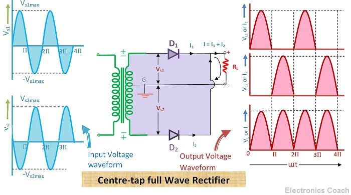
The rectifier circuit consists of a step-down transformer, and two diodes are connected, and they are centre tapped. Thus, this type of rectifier where centre tapping is provided is called centre tap rectifier.
The load resistor is connected, and the output voltage is obtained across this resistor.
Working of Full Wave Rectifier
The input AC voltage supplied to rectify is extremely high. The AC signal is supplied by transmission lines at high voltages because it is economical to supply AC at high voltage. The step-down transformer in rectifier circuit converts high voltage AC into low voltage AC.
In centre tap full wave rectifier two diodes are connected to the central tapping of secondary windings of the transformer. The anode terminals of these two diodes are connected to centre tapping of the secondary winding. Besides, the anode terminals are also connected to load resistor.
When the positive half cycle of AC voltage is applied to the rectifier, the top of secondary winding becomes positive while the bottom of the secondary winding is negative with respect to the top of the winding.
Diode Conduction Mechanism
Thus, diode D1 is forward biased as it is connected to the top of the secondary winding and diode D2 is reverse biased as it is connected to the bottom part of the secondary winding. Thus, the diode D1 will conduct during the positive half of the cycle, and diode D2 will not conduct during the positive half of AC signal.
The diode D1 acts as a short circuit, and diode D2 acts as an open circuit during the positive half of AC signal. When the negative half cycle of the AC signal is applied to the rectifier circuitry the top of secondary winding becomes negative, and the lower half of the secondary winding becomes positive.
Thus, the diode D1 is reversed biased, and diode D2 is forward biased. This happens because the negative voltage on top of the secondary winding makes the anode terminal negative with respect to the cathode in diode D1.
Therefore, in full wave rectifiers, DC voltage is obtained for positive half AC as well as negative half AC. Thus, the name of the rectifier is full wave rectifier is full wave rectifier as it is giving output for the full wave of AC.
Analysis of Full wave Rectifier
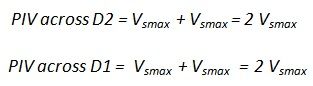
- Peak Inverse Voltage: The peak inverse voltage of full wave rectifier is double to that of half wave rectifier. The PIV (Peak inverse voltage) across D1 is 2Vsmax and PIV across diode D2 is also 2Vsmax. It is double because the PIV across the diode in reverse biasing is the sum of the voltage across half of the secondary winding and load resistor.
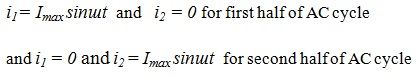
- Peak Current: The value of peak current (Imax) can be derived with the help of instantaneous value of applied voltage and the resistance of the diodes.The value of instantaneous voltage applied to the rectifier circuit can be given as:-
![]()
Let’s assume the forward resistance be Rf ohms and reverse resistance equal to infinity, then the current flowing through the load resistor can be given as:-
The total current i can be obtained by the sum of i1 and i2 for the whole cycle.
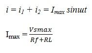
Where Rf is the forward resistance and RL is the load resistor.
The other factors such as output current and output voltage are described below.
- Output Current: The output DC can be obtained by integrating i1 from 0 to Π or integrating i2 from Π to 2Π.
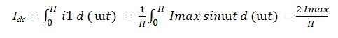
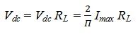
- DC Output Voltage: The average value or DC value of output voltage can be given as the product of output DC and load resistor RL.
- RMS value of Current: The RMS value and effective value of current can be obtained by integrating i21 within limits 0 to Π.
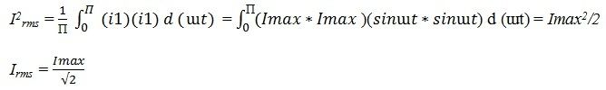
4. RMS value of Output Voltage: The RMS value of the voltage across the load can be obtained by multiplying the RMS value of current and value of load resistor RL.
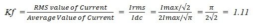
![]() 5. Form Factor and Peak Factor: The form factor (Kf) of full wave rectifier is the ratio of RMS value of current and the average value of current.
5. Form Factor and Peak Factor: The form factor (Kf) of full wave rectifier is the ratio of RMS value of current and the average value of current.
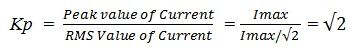
The peak factor (Kp) of full wave rectifier is the ratio between the peak value of current and RMS value of current.
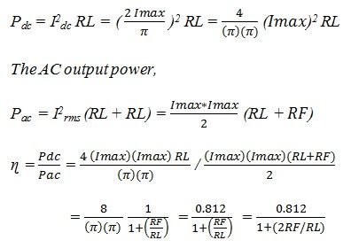
6. Rectification Efficiency: The rectification efficiency of full wave rectifier can be obtained by the ratio of dc power delivered to load and ac power present in the output power.
Advantages of Full Wave Rectifiers
- The rectification efficiency of full wave rectifier is much higher than that of half wave rectifier. It is approximately double to that of half wave rectifier i.e. it is about 81%.
- The filtering circuit required in full wave rectifier is simple because ripple factor in the case of full wave rectifier is very low as compared to that of half wave rectifier. The value of ripple factor in full wave rectifier is 0.482 while in half wave rectifier it is about 1.21.
- The output voltage and output power obtained in full wave rectifiers are much more than that of full wave rectifiers.
- The DC currents flowing in the two halves of the secondary winding of transformer flow in opposite direction, thus, the problem of DC saturation of core is eliminated in full wave rectifiers.
Disadvantages of Full Wave Rectifiers
The full wave rectifiers need more circuit elements than half wave rectifier which makes it costlier.
khalid says
Nice article