Definition: Electrical and mechanical systems possess fixed analogy and there exist similarity between the equilibrium equations of the two. This allows forming such electrical systems whose behavioural characteristics are similar to the given mechanical system. Such systems are known as analogous systems.
More specifically, it is called electrical analogous of mechanical system.
Basically, two systems are analogous in nature when the conditions given below are fulfilled:
- There must be two physically different systems.
- There should have the same differential equation modelling of the systems.
Thus, we can say in order to have an analogous system the conditions given above must be satisfied.
The electrical analogous of the mechanical system is obtained using the below-given methods:
Why do we need Electrical-Mechanical Analogy?
We have already discussed that there must be fixed analogy existing between the two systems along with that the two must have similar equilibrium equations present between them. This is achieved using electrical and mechanical systems. And the representation of the mechanical system in the form of the electrical network is termed as Mechanical Electrical Analogy.
It was proposed by James Clerk Maxwell in the 19th century and permits representing the different functions of the mechanical system as the equivalent electrical system. This is done by forming analogies between mechanical and electrical parameters.
Now the major question is why we are obtaining the electrical analogous of the given mechanical system.
So, basically, producing electrical analogous of a mechanical system is advantageous as it is easier to perform analysis of an electrical system rather than a mechanical system.
This is so because we are more familiar with the analysis of the electrical network as compared to the mechanical one.
Force-Voltage Analogy (Loop Analysis)
It is also known as Direct Analogy. Here first we will see what the elements of the mechanical system correspond in an electrical network.
In a mechanical system, input and output are force and velocity respectively. While in the electrical network these are voltage and current through the elements respectively.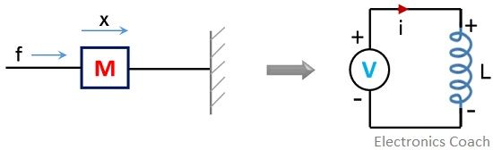
The element ‘mass’ in the mechanical system corresponds to an inductor in the electrical network.![]()
Here, x represents the amount of displacement and v is the velocity.
Further,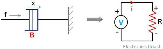
As here B represents the frictional force constant thus corresponds to resistance in the electrical network.![]()
Therefore,![]()
Here V is the voltage
Moreover,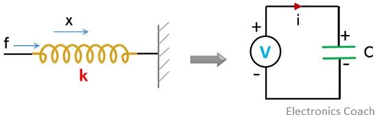
Here, k represents the spring constant, thus it is replaced by a capacitor in the electrical network.![]()
So,![]()
Thus, in case of force-voltage analogy, the points given below are to be necessarily taken into consideration. These are as follows:
- The elements present in series in mechanical system possess the same velocity. Likewise, the serially connected elements in the electrical network have the same current.
- Each existing mass in the mechanical system corresponds to a separate node in it and represents a separate closed loop in the electrical network.
- Also, the number of meshes in the electrical system is equivalent to the number of masses in a mechanical system.
- The elements existing between two masses in the mechanical system represents common elements between two meshes of the electrical system.
Force-Current Analogy (Node Analysis)
Previously we have seen that voltage is regarded as analogous quantity to force. While, in force-current analogy, the current is the analogous quantity in the electrical system to the force in the mechanical system.
Also, as the current was regarded as the output in case of force-voltage analogy, here voltage is regarded as output for force-current analogy.
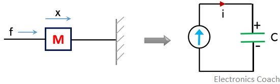
The masses in the mechanical system is replaced by the capacitors in an electrical network.![]()
where x represents displacement and v represents the velocity. Thus,![]()
Here, V shows the voltage.
Now,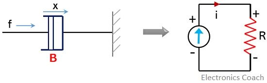
The frictional force B of the damper corresponds to reciprocal of resistance in the electrical network.![]()
Thus,
Furthermore,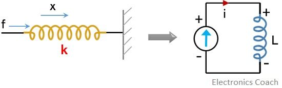
Here, the spring constant k of the mechanical system corresponds to the inductor in the electrical network.![]()
Hence,![]()
Now, let us have a look at the important points to be kept in mind while converting a mechanical system into an electrical network. These are as follows:
- The parallel combination of masses in the mechanical system have similar force, likewise, the parallel combination of elements in the electrical network has the same voltage across them.
- Each separate mass of the mechanical system corresponds to a separate node in the electrical network.
- So, the number of nodes in the electrical network is equivalent to the number of masses present in the mechanical system.
- Like in force-voltage analogy, here also, the number of components in between two separate masses in the mechanical system is also commonly connected in the electrical network between two separate nodes.
A noteworthy point over here is that the elements in serial connection in the force-voltage analogy are parallelly connected in the force-current analogy. Also, those which are in parallel connection in Force-Voltage analogy gets serially connected in the force-current analogy.
This discussion concludes that analogies serve great importance in electromechanical systems when there exists a connection between mechanical and electrical parts.
Arnold wesonga says
Encouraging