The linear power supply and Switch mode power supply, both supplies DC power to electrical and electronic circuits but the similarities end here. The crucial factor which differentiates linear power supply and SMPS is the working procedure. The Linear power supply converts high voltage AC into the low voltage using a transformer and then converts it into DC voltage while the switched mode supply converts AC into DC first then transform that DC voltage into desired voltage.
The Switch mode power supply is also termed as SMPS in abbreviated form. SMPS is most commonly used in mobile chargers, DC motors etc. On the contrary, the linear power supply is used in high-frequency application such as Radio Frequency application etc.
Another significant factor which creates the difference between these linear power supply and SMPS is size. The linear power supply is bulky while the SMPS is light in weight. This makes the SMPS portable and can be easily used anywhere while linear power supply can be used only for laboratory or big electrical and electronic circuit.
We will discuss some more significant differences between linear and switch mode power supply in the comparison chart but before that let’s put light on the roadmap of this article.
Content: Linear power supply and SMPS
Comparison Chart
| Parameters | Linear Power Supply | Switch Mode Power Supply (SMPS) |
|---|---|---|
| Definition | It completes the stepping down of AC voltage first then it converts it into DC. | It converts the input signal into DC first then it steps down the voltage up to desired level. |
| Efficiency | Low efficiency i.e. about 20-25% | High Efficiency i.e. about 60-65% |
| Voltage Regulation | Voltage regulation is done by voltage regulator. | Voltage regulation is done by feedback circuit. |
| Magnetic material used | Stalloy or CRGO core is used | Ferrite core is used |
| Weight | It is bulky. | It is less bulky in comparison to linear power supply. |
| Reliability | More reliable in comparison to SMPS. | its reliability depends on the transistors used for switching |
| Complexity | Less complex than SMPS. | More complex than Linear power supply. |
| Transient response | It possess faster response. | It possess slower response. |
| RF interference | No RF interference | RF shielding is required as switching produces more RF interference. |
| Noise and Electromagnetic interference | It is immune to moise and electromagnetic interference. | Effect of noise and electromagentic interference is quite significant, thus EMI filters are required. |
| Applications | Used in Audio frequency applications and RF applications. | Used in chargers of mobile phones, DC motors etc. |
Definition
Linear Power Supply
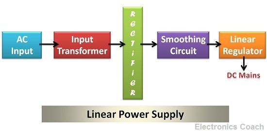
The Linear Power Supply is power supplying circuit which is used in electrical and electronic circuit to supply the DC power to the circuit. It consists of a step-down transformer, rectifier, a filter circuit and voltage regulator.

The AC is always supplied with high voltage because it is economical to supply AC at high voltage. The frequency of the AC signal is very low, i.e. 50 Hz or 60Hz. To reduce the voltage of AC, step down transformer is used. The size of the transformer is large for linear power supply.
The transformer which is used to step down the low-frequency AC signal will be bulky. If the AC signal frequency is high, then a small transformer can be used but in this application the AC signal comprised of low-frequency AC thus, the circuit requires a large size and bulky transformer.
The step-down voltage is then passed to the rectifier circuit to convert it into DC. The DC voltage obtained from the rectifier comprises of AC pulses. Thus, a filter circuit is used to remove the AC ripples.
The obtained DC voltage does not remain constant; it changes with the variation in input voltage or the value of load resistor. This variation in the output voltage is undesirable. Therefore, a voltage regulator is used after filtering the signal.
The voltage regulator consists of the variable resistor the value of which changes according to the output required. This variable resistor produces voltage drop when the output voltage required is low.
Drawback of Linear Power Supply
The drawback of the linear power supply is that the use of voltage regulator requires sink which increases the size of the power supply. The voltage regulator dissipates power due to which ohmic losses occur this increases the temperature, and thus a heat sink is required.
As a consequence of using heatsink and transformer of large size the size of the linear power supply becomes more and this makes the power supply bulky to use. Moreover, dissipation caused by variable resistor decreases the efficiency of linear power supply to 25-50%.
Switched Mode Power Supply
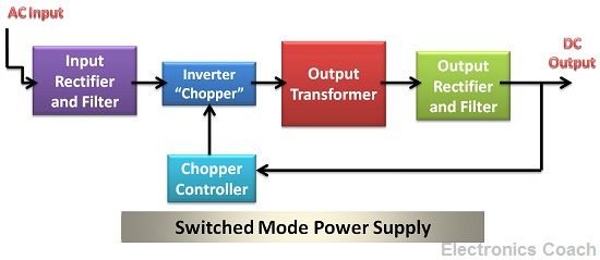
The Switched Mode Power Supply operated on the principle of switching using a MOSFET transistor. It consists rectifier circuit, a filter circuit, chopper, chopper controller, output transformer and a filter circuit.

The principle of working of Switched Mode Power Supply is based on switching technique. The low-frequency AC is converted first into DC signal. Then this DC signal is chopped using chopper circuit. Chopper Circuit consists of MOSFET switching transistor which switches ON or OFF with the help of chopper controller circuit.
The output obtained by Chopper is high-frequency DC signal. Now again a step-down transformer is used to convert this high voltage high-frequency signal into a low voltage signal. The step-down transformer used in this case will be small in size because the transformer used to operate for high-frequency application is small in size.
This is the advantage of using an SMPS (switched mode power supply) circuit. This configuration power supply is not bulky and thus portable. The voltage regulation in SMPS is obtained by the feedback circuit. The feedback circuit takes input from output DC voltage and gives output to chopper controller. The chopper controller generates the gate pulse according to the output DC.
Therefore, voltage regulation in SMPS does not dissipate power and thus do not require sink. This increase the efficiency of SMPS power supply as there is no ohmic loss and the size is also small.The efficiency of SMP
S lies in the range of 65-75%.
Key Differences Between Linear Supply and Switch Mode Power Supply
- The main difference between the linear power supply and SMPS is that linear power supply converts the high voltage of AC into low voltage AC first then the rectification procedure takes place. On the contrary, the SMPS converts the AC signal into DC signal first then the stepping down of voltage signal takes place.
- Linear power supply use voltage regulator for voltage regulation of the output voltage while SMPS uses feedback circuit for voltage regulation.
- Power dissipation also plays a key role in differentiating linear power supply and SMPS. The Linear power supply also dissipates power and thus requires a heat sink, but SMPS do not require heat sink as there is no power dissipation.
- The step-down transformer used in linear supply is bulky while in SMPS the step-down transformer is light in weight.
- The noise disturbance is more in SMPS due to switching action; this makes SMPS inappropriate for audio and radio frequency application. The linear power supply is immune to noise disturbance and thus used in audio and radio frequency application.
- There is the major difference between the efficiency of the linear power supply and SMPS. The efficiency of the linear power supply is low about 20-25% due to ohmic losses while that of SMPS is high, i.e. about 65-75%.
Conclusion
The linear power supply steps down the AC voltage first then converts it into DC while SMPS converts into DC first then uses the step-down transformer to obtain the desired voltage. The SMPS has the drawback that it creates noise interference due to switching. Moreover, switching also creates electromagnetic interferences and RF interferences thus EMI filters, and RF shielding is also used along with SMPS circuit.
shivam says
sir, I have a question, Transformer is working on AC only which we read from the starting, but in SMPS high voltage high-frequency DC is obtained after the rectifier and chopper so how the transformer start working..?? or this transformer is working on DC ..????
Ahmad Wahyudin says
I think the transistor convert it to AC, so
1. From Wall Socket to Bridge Rectifier is AC to DC,
DC output filtered by capacitor.
2. And from Bridge Recfier to Transistor is DC convertes into a high-frequency AC Signal.
3. The high-frequency AC Signal again passing through capacitor for power factor correction and filter which increases the efficiency of the circuit.
4. Then the filtrate high-frequency AC Signal goes to the pulse transformer which steps down the voltage.
5. The AC Voltage is converted to DC by Diode and filtered by capacitor.
mj says
usefull info.