Definition: LVDT, Linear variable differential transformer is an inductive transducer which converts linear motion or displacement into electrical signals. LVDT works on the principle of mutual induction.
Here, the word differential is used as the output value we get is the difference value of voltages produced at the two secondary windings. Displacement provided is directly proportional to the output voltage generated.
Constructional Details of LVDT
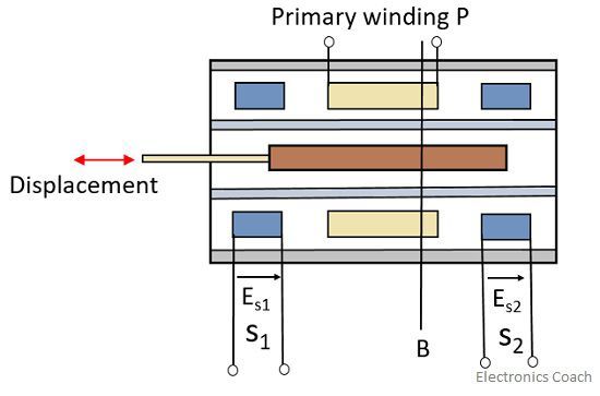
The transformer has a single primary winding P and two secondary windings namely S1 and S2.
The two secondary windings are placed on both sides of the primary winding and the number of turns in both the secondary windings is equal which are wound on a cylindrical former.
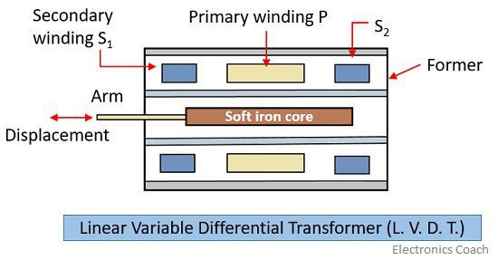
The former consist of a movable soft iron core and usually it is made of high permeability nickel-iron so as to get low harmonics, high sensitivity and low value of null voltage.
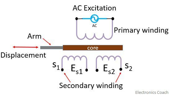
An ac source is provided at the primary winding of the transformer. The frequency range of the source lies between 50 Hz to 20 KHz.
 This ac source produces alternating magnetic fields which produce ac voltages in the two secondary windings.
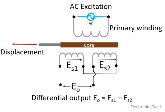
The corresponding output voltage is then generated at the output namely ES1 and ES2 and to get a combined output the two windings are connected in series opposition by which we get the difference of the two output voltages.

The overall assembly of LVDT is placed inside a housing of stainless steel material and the electrostatic and electromagnetic shielding is provided by the end lids.
To reduce the losses due to eddy currents the displacement is measured longitudinally.
Working of LVDT
- When the core is in its normal position or NULL position, the flux linking with both the secondary windings are equal which results in equal induced EMFs in both the coils so we get
Es1 = Es2
Resultantly, Eo= 0

The O position on the above diagram indicates the NULL position.
So, at the null position, the resultant output voltage will be 0.
Further cases arise when the core is moved to either the left or right of the null position.
- Let’s first understand the case when the core is moved towards the left direction of the NULL position.
Position A in the diagram shows the motion of core towards the left direction.
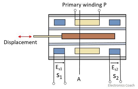
The flux linking in S1 becomes higher as compared to S2 so, the output voltage ES1 will become higher in comparison with ES2.
So, here we will have Eo = Es1 – Es2
Therefore, phase angle ɸ = 0
In this condition, the output voltage will be in phase with that of primary voltage.
- Moving further, when we talk about the movement of the core towards the right of the NULL position which is indicated by point B.
The flux linking in S2 becomes more than S1. Output voltage ES2 will become more as compared to Es1.
Resultantly voltage at the output is given as, Eo = Es2 – Es1
That will be 180﮲ out of phase with the voltage of primary winding.
So from the above results, we can say that the voltage change is directly proportional to the amount of motion of the core.
By noticing the change in the output voltage, we can directly determine the direction of motion of the core.
The differential output voltage provides an estimate of the physical position of the core.
The displacement of the core is simply measured by the amount of voltage at the output as output is the linear function of core displacement from the NULL position.
Now, let’s have a look at the curve between the output voltage and displacement by which we can have a clearer view of the described process.
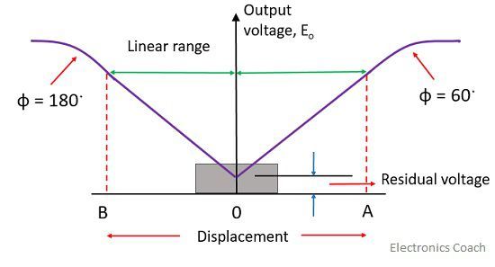
The curve is practically linear over a limited range of displacement from the NULL position to about 5mm but beyond this range, the curve starts to deviate from a straight line.
At NULL position, where Es1 = Es2.
The output voltage ideally should be 0 but actually, there exists a small voltage due to the presence of harmonics in input supply or it can be due to the use of the iron core.
This voltage is generally less than 1% of the maximum output voltage generated.
This residual voltage can also be caused by temperature effect and stray magnetic fields.
Advantages
- LVDT gives high output and it possesses high sensitivity.
- The displacement measurement range of LVDT is very high, it lies in between 1.25 mm to 250 mm.
- LVDT has the ability to withstand higher vibrations and shock levels. They are small and lightweight and provides better stability.
- It shows low hysteresis.
- Power consumption of LVDT is low.
Disadvantages
- Large displacement is required in order to have considerable output.
- Sometimes its performance gets affected by vibrations.
- These are sensitive to stray magnetic fields.
- Change in temperature affects the performance of LVDT.
Applications of LVDT
It acts as a secondary transducer so can be used to measure force, weight and pressure etc. LVDT is used in all such applications where displacements have to be measured.
Leave a Reply