Definition: Half wave rectifier is that in which the half cycle of AC voltage gets converted into pulsating DC voltage. The remaining half cycle of AC is suppressed by rectifier circuit or the output DC current for remaining half cycle is zero.
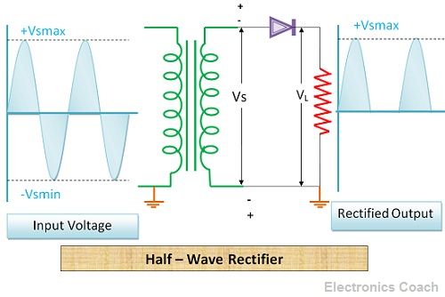
Circuit Diagram of Half Wave Rectifier
The AC input signal is first passed through transformer because the AC signal is generally supplied in high voltage because it is economical to provide AC at high voltage. The transformer present in half wave rectifier is step down transformer which converts the high voltage AC into low voltage DC.
The transformer is followed by a diode and a load resistor. The output current varies with the magnitude of the load resistor.
Working of Rectifier
When the high voltage AC passes from a step-down transformer, it gets converted into low voltage AC.
When the positive half cycle of low voltage AC passes from the diode, it makes the diode forward biased. This happens because the positive signal strikes the P-terminal of the diode and it makes the diode forward biased. Thus, when positive half of AC signal passes the diodes becomes a short circuit. Thus, the current passes through the load resistor, and the voltage drop can be seen across the load resistor.
When the negative half cycle of AC Signal passes through the step-down transformer then due to the phenomenon of mutual inductance, it converts it into low voltage AC. After that, it passes through the diode. When this negative half is passed through the diode, the p-terminal of the diode becomes negative with respect to n-terminal. Thus, the diodes become an open circuit. And the output current across the load becomes zero due to which output voltage also becomes zero.
Thus, during the positive half of AC, the output DC voltage is generated across a load and during the negative half of AC the rectifier switches to OFF state. In this way, the negative half cycle of the signal is suppressed in half way rectifier. It utilizes only half cycle of AC. Thus, it is called half-wave rectifier.
Analysis of Half-Wave Rectifier
- Peak Inverse Voltage: The maximum voltage that the diode can bear in reverse biased mode is called its peak inverse voltage. It is a crucial factor to be considered while designing rectifier system.
![]()
- Peak Current: The maximum current that the diode can withstand in reverse biased condition is called peak current of the diode.
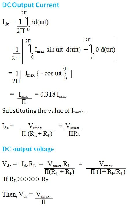
- DC Output Current and DC output voltage: The average value or DC value of the output current and DC output voltage across the load resistor can be given by the following equation below.
- Form Factor and Peak factor: The form factor of half wave rectifier is given by the ratio of RMS value of current and the average value of current.
The peak factor is defined as the ratio between the peak value of current to RMS value of current. 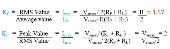
- Output frequency: The output frequency of the rectifier is same as the frequency of the input signal.
fout = fin
- Rectification efficiency: The rectification efficiency of the rectifier is the ratio of the DC output power to the AC input power.
The value of RF is small. Thus, it can be neglected. Therefore, the rectifcation efficiency will be 0.406. In terms of percentage, it can be written as 40.6%. Thus, 40.6% is considered as the maximum possible efficiency of half wave rectifier.
Advantages of Half Wave Rectifier
- Economical: It is low in cost.
- Simple Circuitry: The circuit of half wave rectifier is simple to design.
Disadvantages of Half Wave Rectifier
- Low rectification Efficiency: The rectification efficiency of Half wave rectifier is quite low, i.e. 40.6%. The main reason behind this is power delivered by the circuit of half wave rectifier is only for the duration of positive half of AC cycle.
- High Ripple factor: Ripple factor is given by the ratio of the value of AC current present in the output current of the rectifier and the output dc current of the rectifier. The ripple factor in the case of half wave rectifier is quite high which is undesirable.
- Magnetising Current and hysteresis loss: The magnetizing current and hysteresis losses occur due to DC saturation of transformer core. Due to this magnetizing current harmonics are generated, and it is undesirable for the smooth operation of half wave rectifier.
Half Wave rectifiers convert only half wave of AC either positive or negative half into DC. If we want to convert entire cycle of AC into DC then we need Full wave rectifier.
Leave a Reply