Definition: Phase modulation is another type of angle modulation in which the phase of the carrier wave is changed according to the amplitude (magnitude) of the message (modulating) signal.
In phase modulation of an analog signal, the phase change is a continuous back and forth movement. While in case of digital signal there exist an abrupt change in the phase of the carrier signal. The phase modulation of the digital signal is generally known as phase shift keying.
The process of phase modulation is somewhat the same as that of frequency modulation. As whenever there is any variation in the phase of the carrier signal, then, the frequency of the signal also shows variation.
Theory of Phase Modulation
In phase modulation, the amplitude of the carrier signal remains unchanged while phase change occurs. And we have already mentioned that with the change in phase, the frequency of the signal also shows variation.
Thus it can be said that while phase modulating any signal, the phase, as well as the frequency of the carrier signal, shows variation.
Let us proceed further to understand how a carrier signal gets phase modulated.
The figure below shows a sinusoidal message signal that is to be transmitted from an end to another, a carrier signal which is to be phase modulated. And the last image in the above figure represents the phase modulated signal.
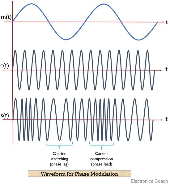
Here, it is clear from the above figure that when the amplitude of the sinusoidal signal starts to increase and reaches the maximum value, then the phase lead of the carrier signal gets increased.
Due to this a compression in the carrier signal is noticed. This resultantly increases the frequency of the signal.
However, when the amplitude of the modulating signal starts falling and attains a minimum value, then the phase lag of the carrier wave occurs. Thereby resultantly causing stretching of the signal. Due to this, the frequency of the signal gets increased.
So, in this way, we can say that with the change in phase of the signal during phase modulation, the frequency of the signal also shows some variation.
For a sinusoidal signal, the modulated signal is somewhat similar in case of both frequency and phase modulation. While in the case of the square wave signal, the case is not exactly the same.
Now the question emerges why this is so? For this look at the figure shown below, where, the message signal is a square wave and the frequency modulated signal is different from that of phase modulated signal.
As we can see for a square wave signal, in frequency modulation, the frequency of the modulated signal is high when the magnitude or amplitude of the message signal is positive.
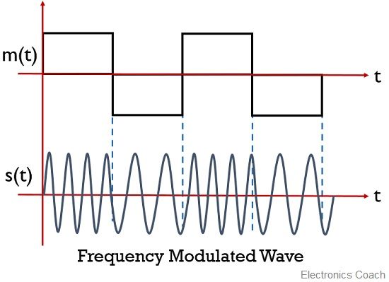
While, for the negative amplitude of the message signal, the frequency of the modulated signal is noticed to be low.
But when we consider the same square wave message signal for phase modulation. Then the phase modulated signal undergoes phase shift keying as the message signal is a digital signal.
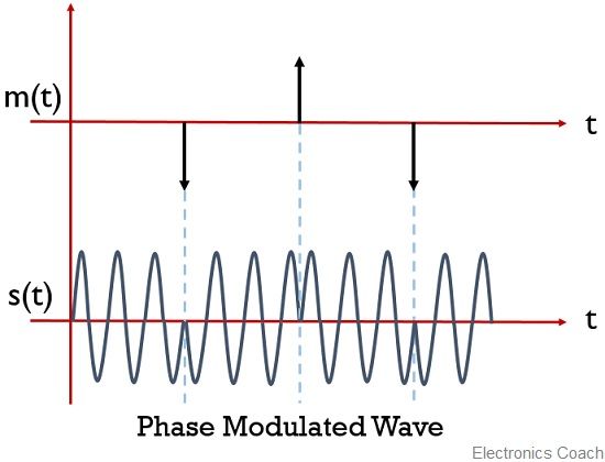
As when the signal moves from positive to negative amplitude then negative phase reversal exists. While, when the message signal shows movement from negative to positive amplitude then positive phase reversal takes place.
Hence we cannot say that for any type of message signal, the frequency and phase modulated signal shows similarity in the waveform.
Expression of Single Tone Phase Modulation
As we have already discussed that the phase angle of the carrier signal is changed in accordance with the amplitude of the message signal.
Suppose the voltage of the carrier signal is given as
c(t) = VC sin (ωct + φ)
So, the phase modulated wave will be
s(t) = VC sin (ωct + φm sin ωmt)
: φm denotes the maximum change in the phase of the carrier signal in accordance with the highest amplitude of the message signal.
So, for simplicity, we can write,
s(t) = VC sin (ωct + mp sin ωmt)
: φm = mp = modulation index
Deviation sensitivity of Phase Modulation
The message signal is
x(t) = Vm cos (ωmt)
The phase deviation is given as
θ(t) α x(t) rad
θ(t) = Kp x(t) rad
: Kp is the deviation sensitivity
Kp = rad / V
Also, the modulation index of a phase modulated wave is given as
mp = KpVm
Advantages of Phase Modulation
- The process of phase modulation is quite east than frequency modulation.
- This technique is used to determine the speed of the mobile target. Because for this the carrier is required to be constant and this is obtained in case of phase modulation.
- A phase modulated signal is more immune to noise effects.
Disadvantages of Phase Modulation
- In order to raise the modulation index of a phase modulated signal, frequency multipliers are needed.
- The system cost is quite expensive.
- Sometimes phase ambiguity exists when the modulation index exceeds a certain value.
Applications of Phase Modulation
This technique is widely used in the transmission of radio waves. This process is also employed in wireless signal transmission like satellite and Wi-Fi transmission etc.
Leave a Reply