Definition: A digital modulation technique that transmits data by varying the phase of the carrier wave in accordance with the digital modulating signal, is called Phase Shift Keying (PSK).
The easiest form of PSK is BPSK i.e., binary phase shift keying. However, PSK can be extended to 4 level and 8 level PSK that totally depends on the need of the system.
Principle of BPSK
BPSK technique is the simplest among all the PSK techniques. In this, each signalling element is represented by a single data bit. Here, the carrier undergoes two phase reversal such as 0° and 180°. In phase shift keying the digital bit sequence is first converted to NRZ bipolar signal which directly modulates the carrier wave.
Expression for BPSK
Let us consider the carrier wave is given as
s(t) = A cos (2πfct)
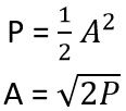
The peak of the carrier wave is represented as A when the load resistance is assumed to be 1 ohm as standard, the power dissipated is given as,
 A change in phase by 180° is noticed with the corresponding change in the bit sequence.
Assume the carrier for symbol 1 is given as
![]()
Similarly, in the case of symbol 0, we have,
![]()
: π represents the phase shift of 180°
As we know cos (ɸ + π) = – cos ɸ
Thus, s2(t) can be written as,![]()
Hence, BPSK signal can be written as,
![]()
: b(t) will be +1 in case of transmission of binary 1 and
b(t) will be -1 in case of transmission of binary 0.
BPSK modulation
The figure below shows the block diagram for the generation of a BPSK signal.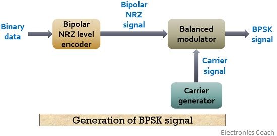
As we can see here that the system consists of NRZ encoder along with product modulator and carrier generator.
The binary message signal is fed to the bipolar NRZ level encoder that converts the Binary data input into equivalent bipolar NRZ sequence m(t). This bipolar NRZ signal is fed to the balanced modulator along with the carrier wave.
Thus, the binary signal modulates the carrier wave that generates a phase shifted modulated signal termed as BPSK signal.
Let us have a look at the figure below that shows BPSK generated waveform with the binary bit sequence and carrier wave.
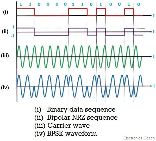
Here, (i) represents the binary bit sequence, the next represents the bipolar NRZ sequence m(t) that is used to modulate the carrier wave represented in (iii). The resultant BPSK signal is then achieved.
Here, as we can see that, the figure shows phase reversal when the bit sequence gets changed either from 1 to 0 or from 0 to 1. When the bit sequence changes from 0 to 1 then we noticed a positive phase change whereas, when the bit sequence changes from 1 to 0 then a negative change of phase is noticed.
BPSK Demodulation
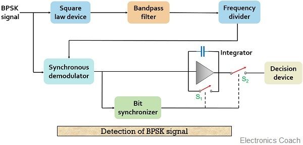
The block diagram for the coherent detection of BPSK signal is shown below:
Let us consider, the signal at the input of the receiver is![]()
The phase shift ɸ is based on the time delay in between transmitter and receiver.
The signal is then fed to a square law device that provides
cos2(2πfct + ɸ) as its output.
Here, only the carrier of the signal is taken into consideration thus the amplitude is neglected.
As we know,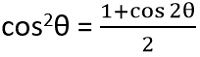
Expanding the carrier as the above mathematical identity,
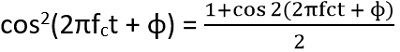
Or we can write,
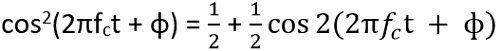
: dc level is showed by ½
This signal is then fed to the BPF as we can see in the diagram above. This BPF has a centre frequency of 2fc, eliminates the dc level hence, generates output as
cos 2 (2πfct + ɸ)
This signal is then further fed to a frequency divider unit. As it is frequency divider by 2 thus generates a carrier with frequency fc.
This carrier is then multiplied with the input signal,
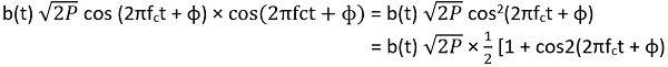
thereby generating the output as,
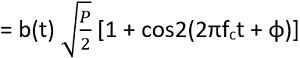
This signal is then given to the integrator and bit synchronizer unit. The signal is integrated over the 1-bit period by the integrator by making use of bit synchronizer. It manages the bit duration. After a completed bit duration, synchronizer closes S2 and the output of the integrator acts as input to the decision device.
Further, processing continues when S2 gets open and S1 gets closed for some time, resetting the voltage of the integrator to 0. Then the next bit is integrated by the integrator and the cycle repeats. The decision device then generates the equivalent binary data, the actual message signal.
Advantages of Phase shift keying
- It allows more efficient transmission of radio frequency signal.
- Better noise immunity is noticed in the case of BPSK technique.
- Less bandwidth is utilized by the BPSK signal in comparison to BFSK.
Disadvantages of Phase shift keying
- Detection of a BPSK signal is quite complex.
- Phase discontinuity sometimes leads to variation in amplitude of the signal.
Applications of Phase shift keying
PSK modulation technique finds its applications in biometric operations, Bluetooth connectivity, wireless local area networks and in telemetry operations.
Leave a Reply