Definition: Amplitude Modulation is a technique by which the amplitude of the carrier wave is changed according to the signal wave or modulating signal. Among various modulation schemes, amplitude modulation is the simplest and oldest modulation technique.
Basically, the information that is carried by the low frequency modulating signal is superimposed on the carrier wave of high frequency by varying the amplitude of the carrier. Thus it is termed as amplitude modulation.
Theory of Amplitude Modulation
Let us now move further in order to have a detailed discussion about how a signal gets amplitude modulated.
It is not an easy task to transmit a message signal directly as with the propagation of the signal, several factors degrade its quality. This sometimes leads to the reception of a highly deteriorated signal at the receiver. Thus modulation technique was introduced that is proved advantageous in various formats.
Amplitude modulation is the straightforward way to modulate a signal. In which, the amplitude of the informationless carrier wave is changed according to the message signal without changing the other factors associated with the carrier wave such as frequency and phase.
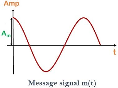
The figure below shows the modulating signal having amplitude Am
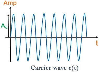
This message signal is to be transmitted to a certain distance, by making use of carrier signal which is shown below:
After amplitude modulation, an amplitude modulated wave is achieved, which is shown below:
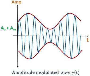
This amplitude modulated wave contains a time-varying amplitude that is termed as an envelope. This envelope has the similar shape as that of the message signal.
Mathematical Expression for Amplitude Modulation
Let us consider a modulating signal m(t), which is given by,
m(t) = Am cos ωmt
and the carrier signal c(t), given by the expression
c(t) = Ac cos ωct
Now, when the amplitude of the carrier is changed according to the message signal, an amplitude modulated wave is generated which is given by
y(t) = A0 cos ωct
Here, A0 = Ac + m(t)
Thus, modulated wave is given as,
![]()
Now, the question that strikes our mind is up to what extent a carrier is amplitude modulated. So, the answer to this question is the modulation index.
The modulation index is the term that shows the amount by which a carrier signal is amplitude modulated.
Considering equation 1 again
y(t) = (Ac + Am cos ωmt) cos ωct
Taking Ac out of the above equation a common factor, we will have
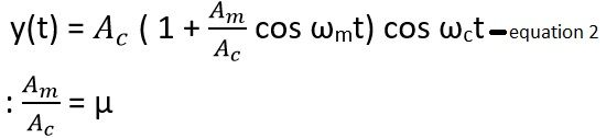
which is termed as the modulation index.
Thus, we can say the modulation index is the ratio of the amplitude of the message signal and the carrier signal. Hence, one can easily calculate the modulation index, when the amplitudes of the two signals are known.
We can also determine the modulation index with the help of modulated wave.
Assume, Amax to be the maximum amplitude of the modulated signal and Amin to be the minimum amplitude of the modulated signal.
Amax is achieved if cos ωmt = 1
Amax is given as
![]()
Amin is achieved, if cos ωmt = -1
Amin is given as
![]()
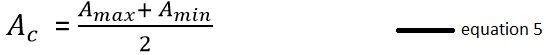
On summing equation 3 and equation 4,
Amax + Amin = Ac + Am + Ac – Am
Amax + Amin = 2 Ac
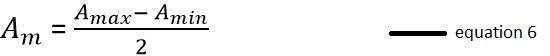
On subtracting equation 4 from equation 3
Amax – Amin = Ac + Am – Ac + Am
Amax – Amin = 2 Am
Dividing equation 6 by equation 5
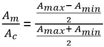
Thus, the modulation index is given as
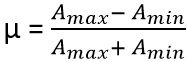
When the value of µ is 1, then it is said to be an ideal modulation.
The value of the modulation index classifies the modulated wave into 2 categories.
Concept of Linear and Overmodulation
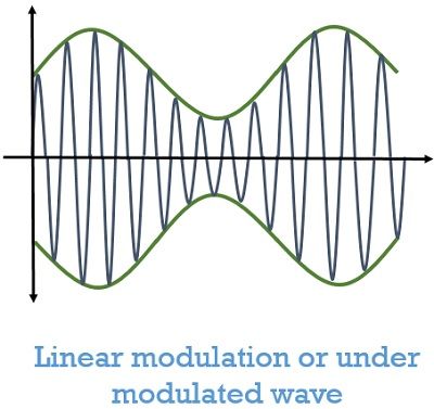
Linear modulation: When the value of the modulation index is less than 1 then it is said to be a linear or under-modulated wave. The figure below shows the linear modulation of amplitude modulated wave.
Overmodulation: When the value of the modulation index exceeds more than 1, then over modulation takes place. As we can see in the figure shown below: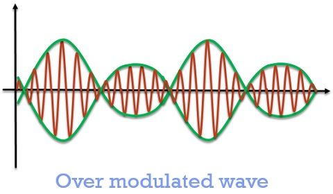
Overmodulated wave must be avoided as in this case, as here at some certain point of time, the amplitude is shown 0. This shows that at this point the amplitude of the carrier is not changed according to the message signal. That leads to signal distortion.
Transmission Efficiency
Transmission efficiency is the ratio of power for the transmission of the message signal to the total power transmitted.
As we know that the transmitted signal is a modulated one, which contains both message signal along with the carrier wave. This carrier wave is of no use after the signal has reached its destination and must be separated from the message signal.
Thus, total transmission power and the power that is required for transmission of message signal only are different.
Advantages of amplitude modulation
- It is the simplest modulation technique.
- Demodulating the modulated wave is easy.
- It is a Low cost technique.
Disadvantages of amplitude modulation
- High signal attenuation due to noise.
- It provides low efficiency.
It is to be noted here that amplitude modulation is performed only to transmit the signal and the modulated wave is again demodulated at the receiver in order to have the original information carrying signal.
Leave a Reply