Definition: An op-amp detector that has the ability to detect the change from positive to negative or negative to a positive level of a sinusoidal waveform is known as a zero crossing detector. More specifically, we can say that it detects the zero crossing of the applied ac signal.
It is basically a voltage comparator whose output changes when the input signal crosses the zero of the reference voltage level. Thus it is named so.
It is also known to be a square wave generator as the applied input signal is converted into a square wave by the zero crossing detector.
Circuit Diagram of Zero Crossing Detector
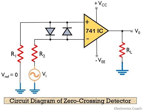
The figure below represents the circuit of a zero crossing detector using inverting op-amp:

Here, the input signal Vi is provided to the inverting terminal of the op-amp while the non-inverting terminal is grounded by making use of two resistors R1 and R2.
As we can see that analog input signal is provided at the inverting terminal of the op-amp. Thus, the waveform of the signal at the output will hold reverse polarity. This we will discuss under working of the detector.
Working of Zero Crossing Detector
As we have already discussed that it detects the point where the input signal crosses zero of the reference voltage level. For every crossing, the saturation level of the output signal changes from one to another.
Let us consider the circuit given above in order to understand the working.
As we have already mentioned that the reference level is set at 0 and applied at the non-inverting terminal of the op-amp. The sine wave applied at the inverting terminal of the op-amp is compared with the reference level each time the phase of the wave changes either from positive to negative or negative to positive.
Firstly, when positive half of the sinusoidal signal appears at the input. Then the op-amp comparator compares the reference voltage level with the peak level of the applied signal
![]()
And we know the reference level is 0, thus
![]()
So, we will have
![]()
Secondly, in case of the negative half of the sinusoidal signal, the op-amp comparator again compares the reference voltage level with the peak of the applied signal.
As this time the circuit is dealing with negative half of the signal, thus the peak will have a negative polarity.
Again
![]()
Thus,
![]()
So, we get
![]()
In this way, the zero crossing detector detects the change in the level of the applied signal.
Input and Output Waveform
From the beginning, we are mentioning that a zero crossing detector is also known to be a square wave generator. As the output of the window comparator is nothing but a square wave.
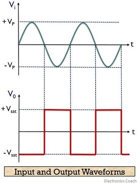
Let us now have a look at the input and output waveform of a zero crossing detector:

As we have recently discussed that V0 for the positive half of the applied signal is – Vsat,
This is the reason why we have achieved negative half of the square wave at the output when positive half of the sinusoidal signal is applied. While V0 for the negative half of the sinusoidal signal is + Vsat,
Thus positive half of the square wave is obtained at the output for the negative half of the sinusoidal signal. This is clearly shown in the waveform representation.
So, on observing the output waveform we can say that the output reflects the presence of input signal above or below the reference level i.e., 0 volts.
Applications of Zero Crossing Detector
Zero crossing detectors widely find applications in electronics circuits mainly for switching purpose and in phase locked loop. Also, these are used in frequency counters and in phase meters.
It can also be used as phase meters, as it can be used to measure the phase angle between two voltage applied at its terminals.
Leave a Reply