A type of controller in a control system whose output varies in proportion to the error signal as well as with the derivative of the error signal is known as the proportional derivative controller. It is also known as a proportional plus derivative controller or PI controllers.
This type of controller provides combined action of both proportional and derivative control action.
We know that the presence of controllers in any control system improves the performance of the overall system. So, the presence of two distinct control action generates a more precise system.
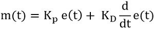
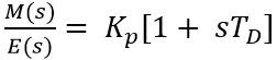
For the PD controller, the output is given as:
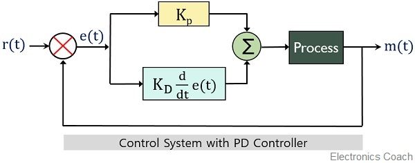
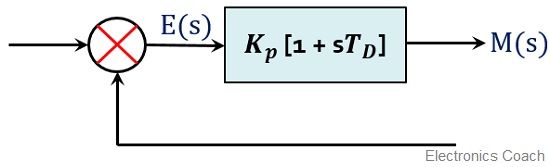
The block diagram of a control system comprising of PD controller is given below:
What are Proportional and Derivative Controllers?
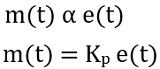
Proportional controller: It is a type of controller in which the output of the controller varies in proportion with the input. Mathematically it is written as:
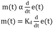
Derivative Controller: In the derivative controller, the control action is such that the output of the controller is proportional to the rate with which the error signal is changing with time.
So, mathematical expression is given as:
Earlier the control action of derivative controllers was individually used in a control system. But the merger of the proportional controller with a derivative controller provides a more efficient system. As here the disadvantages associated with the derivative controller get eliminated by a proportional controller.
We know that derivative controllers are basically designed with the aim that its output changes with the changing error signal.
However, it does not show variation in the case of constant error signal. The reason behind this is that when the value of the error signal remains constant then its rate of change with time will be 0. So, in order to consider even constant error signal, derivative controllers are used in conjunction with proportional controllers.
The presence of a derivative control action with a proportional controller enhances sensitivity. This helps in producing early corrective response for even small value of error signal thereby increasing the stability of the system. But we are also aware of the fact that the derivative controller increases steady-state error. While the proportional controllers reduce the steady-state error.
Therefore, to enhance the stability of the system without affecting the steady-state error, a combination of proportional and derivative controllers is used.
Proportional Plus Derivative Controllers
The mathematical expression for proportional derivative controller combining the action of proportional and derivative controller is given as:
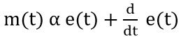
So, on eliminating the proportionality sign, the constant of proportionality gets added with the error signal as well as the derivative of the error signal. Thus
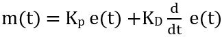
: Kp is the constant of proportionality of error signal,
KD is the constant of proportionality of derivative of the error signal.
In order to have the transfer function of the PD controller, we need to consider the Laplace transform of the above equation. Therefore,
![]()
Further
![]()
We know transfer function is given as output by input and for controllers the input is error signal and output is controller output.
So, on transposing E(s), we will have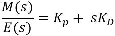
Further, on taking KP as common from the RHS, we will get
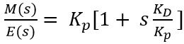
Therefore, we can write it as
This is defined as the gain of the PD controller.
: TD = KD/KP
Thus in the form of block diagram, PD controller with gain is represented as:
Effects of Proportional Derivative Controller
We have discussed the reason behind using the combined control action of the proportional and derivative controller.
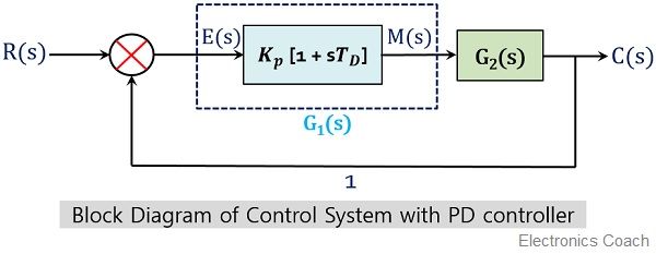
Let us now see how a PD controller affects the system. Consider the block diagram of a PD controller with unity negative feedback given below:
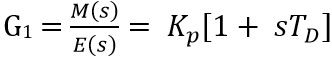
 We have recently evaluated the gain of the PD controller as:
Suppose G2(s) be the open-loop gain of the system given as:
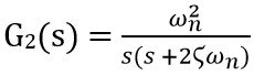
By observing the open-loop gain it is clear that stability is very less due to the absence of zeroes.
We know steady-state error shows dependency on type number (which is nothing but the number of poles at the origin). As our aim is to keep the steady-state error invariable thus the type number is kept constant. And for this, we will keep the power of ‘s’ as it is in the denominator.
However, to enhance the stability of the system, ‘s’ must be introduced in the numerator. So, to achieve this, the PD controller is incorporated into the system.
Thus the gain of the system will be given as:
![]()
Hence on substituting the values of G1 and G2 we will get,
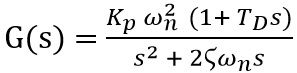
We know that to improve the transfer function of the system, the transfer function of the PD controller must be utilized.
Thus for the overall system, the transfer function is given as:
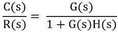
For a system with unity negative feedback, H(s) = 1. Therefore,
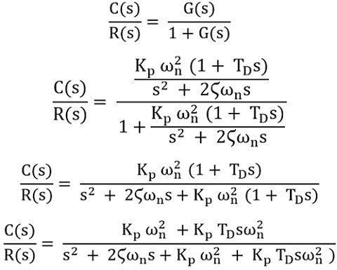
On simplifying further,
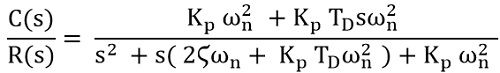
Since we know that TD = KD/ KP, thus, we can substitute KP.TD as KD in the above equation,
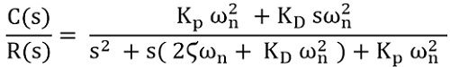
On comparing the open-loop gain with the closed-loop gain of the system we observe that zeroes are not present (s term in the numerator) in case of open-loop gain. While it gets introduced in the gain of the closed-loop system. Thus the stability is increased.
By analyzing the denominator of open-loop and closed-loop gain, it is clear that the type number of the system is undisturbed thereby indicating no change in the steady-state error of the system.
Hence in this way, the overall transient response of the system shows improvement.
Leave a Reply