A type of controller in which the output of the controller varies in proportion with the error signal, integral of the error signal and derivative of the error signal is known as the proportional integral derivative controller. PID is the acronym used for this type of controller.
Proportional plus integral plus derivative controller is sometimes referred as a 3-mode controller, as it combines the controlling action of proportional, integral as well as derivative controller altogether.
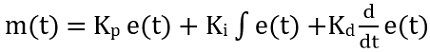
The combination of all the three types of control action improves the overall performance of the control system, in order to provide the desired output in an effective manner. The output of a PID controller is given as:
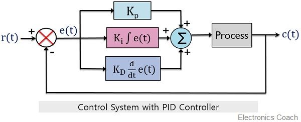
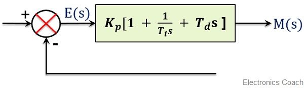
Here we have a block diagram of the PID controller:
What are Proportional, Integral and Derivative Controllers?
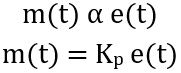
Proportional controller: The controller whose output shows variation in proportion with the error signal is known as a proportional controller. It is given as:
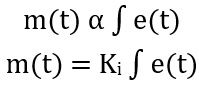
Integral Controller: In this case, the output of the controller varies with the integral of the error signal. Thus is given as:
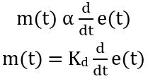
Derivative Controller: A derivative controller generates an output that varies proportionally with the derivative of the produced error signal. It is represented as:
In the previous article, we have discussed how the performance of the system gets improved when proportional integral and proportional derivative control action were used in the controller of the control system.
We have already discussed in PI controllers, the combined action of proportional and integral controller acts as an advantageous factor for the overall control system as it decreases the steady-state error. Thus it improves the steady-state response of the overall system. However, in this case, the stability of the system remains unchanged as it does not show improvement.
We are also aware of the fact that a PD controller enhances the sensitivity of the system. This is so because in this case, the output of the controller varies proportionally with the error signal as well as a derivative of the error signal. Thus even for a small rate of change of error the output shows significant variation.
In this way, the early corrective response is produced for the system hence the stability of the overall system gets improved.
However, it is noteworthy in the case of PD controllers that the steady-state error remains unaffected in its case.
More simply we can say derivative controllers give rise to steady-state error. While integral controllers generate stability error. So, to eliminate the respective disadvantages of both types of controllers PID controllers are used.
Hence a PID controller produces a system, that provides increased stability with a reduction in the steady-state error.
Proportional Plus Integral Plus Derivative Controller
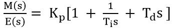
The controlling action of PID controllers involving the control action of the proportional, integral and derivative controller is mathematically represented as:
![]()
On removing the sign of proportionality, the constant of proportionality gets added. Thus, we can write it as:
![]()
Here Kp is proportionality constant for the error signal,
Ki is the proportionality constant for integral of the error signal and
Kd is the proportionality constant for the derivative of the error signal.
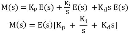
Further to determine the transfer function of the controller, the time domain function must be converted to the frequency domain. Therefore, considering the Laplace transform of the above equation, we will get
![]()
Further
We know that the transfer function is represented as output by input. Thus the transfer of the controller will be given as,
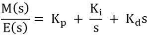
On further simplification
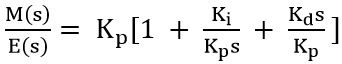
Consider, Kp/Ki = Ti and Kd/Kp = Td and substitute in the equation given above, we will get,
So, further 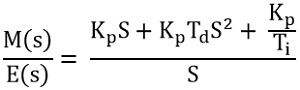
Since, Kp/Ki = Ti therefore Kp/Ti = Ki
And Kd/Kp = Td, therefore, Kd = Kp Td
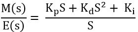
This is given as the simplified transfer function of the PID controller.
The PID controller in the form of block diagram with gain is represented below:
Effects of PID Controller
We have already discussed in the beginning the reason behind incorporating a PID controller in a control system.
Let us now see how the PID controllers affect the control system. So, for this, consider the block diagram of the control system with a PID controller:
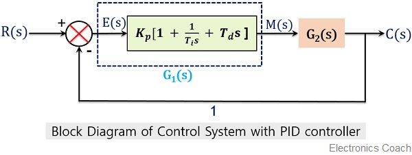
Suppose the gain of the PID controller is G1(s), given as:
![]()
Let G2(s) be the open-loop gain of the system given as:
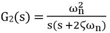
The absence of zeroes in the open-loop gain shows low system stability. So, we will find the closed-loop gain of the system with a PID controller.
The overall gain of the system will be given as:
![]()
On substituting the values, we will have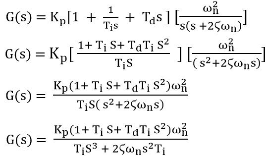
The transfer function of the overall system is given as: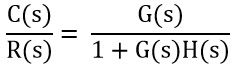
For a system with unity negative feedback, H(s) = 1. Thus the transfer function will be given as:
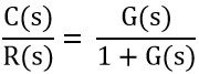
On substituting the overall gain of the system in the above equation, we will have,
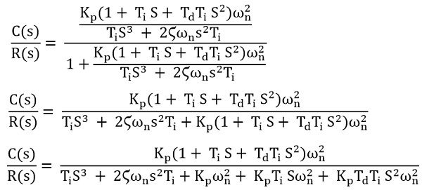
Taking Ti common from the denominator,
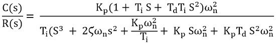
Since Kp/Ki = Ti thus Kp/Ti = Ki
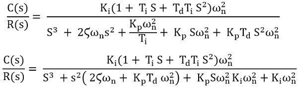
This is defined as the gain of the control system with a PID controller.
We know that the open-loop gain of controller is given as:
As there is no ‘s’ term present in the numerator. Thus this represents the absence of zeroes.
But when the open-loop gain is compared with the gain of the overall control system with a PID controller, then we notice that 2 zeroes are present in the numerator of the gain of the control system.
It is clear that s3 term is present in the denominator also. This represents the presence of the pole at the origin.
Basically one zero of the numerator gets nullified by the one pole of the denominator. However, the presence of one zero at the numerator increases the stability of the overall system. While two poles at the origin reduces the steady-state error of the system.
Thus in this way on combining proportional, integral and derivative control action, the desired system response can be achieved.
Leave a Reply