Definition: A lag compensator is a circuit that is designed to generate a steady-state sinusoidal signal having a phase lag to the applied input sinusoidal signal. This can also be stated in a way that it is a circuit that is when provided with a sinusoidal input produces a sinusoidal output signal whose phase lags the applied input.
It is sometimes referred as a lag network.
We know that compensators are used in the control system in order to have the desired output. Basically, the desired output through a control system is achieved when the system properly controls the ongoing process inside it.
However, for this purpose also, the system specifications must be proper.
When certain parameters of the system are changed then this sometimes leads to variations in the system specifications, and this causes malfunctioning of the control system. This is the reason the control system must be resigned.
So, redesigning a control system to produces accurate results by adding an external physical device is known as compensation. And the physical device added to the system is known as a compensator.
This addition of the external device introduces poles and zeros in the transfer function of the system. This varies the performance parameter of the system.
Phase Lag Compensator
We have already discussed in our previous article that a phase lead network generates an output with a leading phase than that of the supplied input.
The phase lag compensator performs just reverse operation as that of the lead compensator. It introduces a phase lag in the steady-state output when the input signal is provided to it.
A lag compensator has zero and dominating pole. A dominating pole is the pole present nearest to the origin in comparison to all the other poles in the s-plane. And the poles and zeros must be present on the negative real axis.
The figure below represents the phase lag network: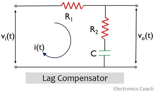
First, we will apply KVL in the above circuit. Suppose i(t) is the current flowing through the loop. Thus, for loop 1,![]()
We know to determine the response of the system; its transfer function must be determined.
The transfer function is given as the ratio of output to input in the frequency domain.
So, further we will take the Laplace transform of the above equation,![]()
Now considering loop 2,![]()
Again considering the Laplace transform:![]()
Further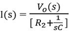
On substituting the above value of I(s) in Laplace equation of input loop, we will get,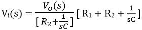
On simplifying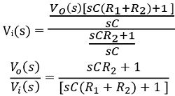
Further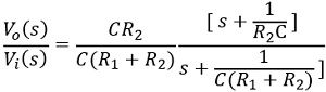
The general expression is given as: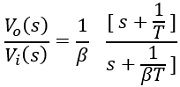
Hence, on comparison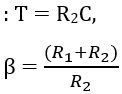
Hence, this shows that the zero of the lag compensator will be present at s = -1/T and pole will be at s = -1/βT.
Since β is greater than 1, thus pole of the transfer function is more dominating than the zero. The figure below represents the pole-zero plot of the lag compensator:
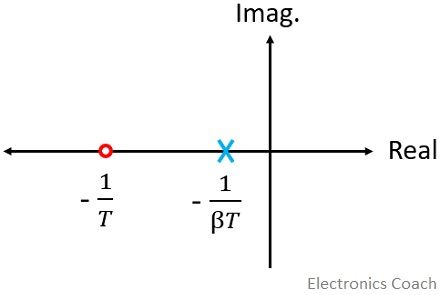
Generally, β is considered as 10. This is the reason when lag compensator is serially connected to the control system; then a negative phase angle is introduced.
Lag Angle
We have discussed the transfer function of the lag compensator. Now proceeding towards determining the maximum lag angle offered by the compensator at a certain frequency.
Since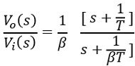
Further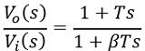
Substituting s = jω
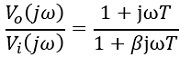
Therefore, the magnitude will be given as: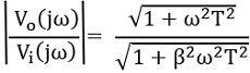
So, the phase angle will be:![]()
The phase angle of the lag compensator shows similarity with the lead compensator, which is given as:![]()
where the only difference is β>1
Now we will determine the particular frequency at which phase angle ɸ is maximum,
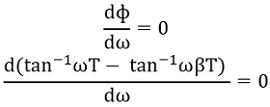 Thus
Thus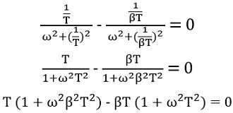
Further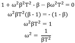
So, we will get,![]()
Furthermore,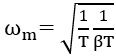
Thus, it is clear that at this particular frequency, phase lag will be maximal.
Here ωm is the geometric mean of two corner frequencies,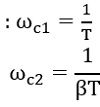
Advantages of Lag Compensator
- A phase lag network offers high gain at low frequency. Thus, it performs the function of a low pass filter.
- The introduction of this network increases the steady-state performance of the system.
- The lag network offers a reduction in bandwidth and this provides longer rise time and settling time and so the transient response.
Disadvantages of Lag Compensator
- In lag compensator, the attenuation offered by it shifts the gain crossover frequency to a lower point, thereby decreasing the bandwidth.
- Though the system response is longer due to decreased bandwidth; however, the response is quite slow.
- A control system with a lag network shows more sensitivity towards variation in the parameters than a system with a lead network.
- Like in lead compensator, in lag compensator also, due to the addition of external network, some attenuation is introduced. So, the overall gain must be increased to handle the attenuation. But this will increase the requirement of more elements and so the cost and space requirement.
- A lad compensator somewhat acts as a proportional plus integral controller hence adversely affects the stability of the system.
It is to be noted in case of lag compensator that, it operates in a way to provide attenuation to high-frequency range. Thus in lag compensation, phase lag angle is of no justifiable use.
Leave a Reply