We know that a system generally holds multiple elements that combinedly act as a single unit in order to execute a certain task. We have also discussed, that in a control system, the various connected elements direct or control itself or any other system to have a specific output.
The incorporation of various entities as a single unit in a system makes the system quite complicated for analysis. So, block diagram representation of control system is used in order to show a complex system in an easy manner.
Block Diagram of a Control System
Basically block diagram of a control system pictorially represents a system. By using visual illustration, even a very complex system can be simplified for the purpose of analysis.
The block diagram representation of a system is nothing but an interconnection of multiple elements of the system. This interconnection using blocks allows a convenient analysis of the system.
Now the question arises, how the block diagram representation simplifies the system?
So basically, mainly the block diagram of a system is generated so that one can apply the transfer function approach.
By doing so, the transfer function of each element can be determined and thus the system can be analyzed in a simple manner.
Thus, in a simple term, we can say that a block diagram is the pictorial representation of a system in which the different elements of the system are sequentially connected.
This sequential arrangement of the elements allows the easy determination of the relationship between cause and effect that exists between input and output of the system.
We know that the block diagram representation of the open-loop and the closed-loop system is different as the closed-loop system contains a feedback loop.
This feedback loop helps to provide a part of the input back to the input.
Elements of Block Diagram
Functional Block: The functional block represents the elements or components of the control system.
Basically, in block diagram representation, each element of the control system is represented by a block. This block is the functional block.
Thus we can say that a specific block represents the mathematical operation performed by that element on the input in order to achieve the desired output.
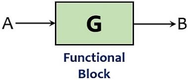
The transfer function of the block shows the mathematical function of the element present as a block.
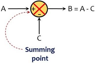
Summing Point: The point in the block diagram representation where the multiple signals are compared is known as the summing point.
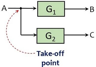
Take-off Point: In a closed-loop system, part of the output is fed back to the input that acts as feedback for the system. So, the take-off point is that point from where a portion of the signal is taken as feedback for the system.
It is noteworthy at the time of drawing the block diagram of a control system that the interconnection of blocks, summing points, and take-off points must be done exactly in the way in which the elements are present in the practical system.
The elements in the block diagram are connected using lines or branches. While arrowheads represent the direction of flow of signal inside the block as the signal flows only in a unidirectional path.
Thus we can say the block diagram is a unilateral illustration of the system.
Canonical form of Control System
We know that a closed-loop system uses a feedback loop thus is considered better than the open-loop system.
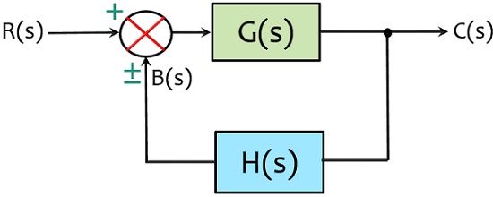
A block diagram representation in which there is only one forward and feedback block along with a single summing point and take-off point is the simplest form of closed-loop control system. It is also known as the canonical form of a closed-loop system.
The figure below shows a simple closed-loop system: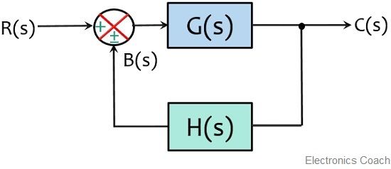
Example of Control System
Let us take an example in order to understand how a practical system can be converted in the form of a block diagram.
Suppose we have a liquid level system as shown below and we have to represent this system in the form of a block diagram with the respective blocks for each element.
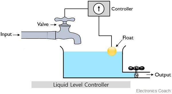
So, firstly we have to identify the overall elements present in the system. As we can see that the above system contains a controller, a valve, a water tank, and a float.
Basically, this system operates in a way that water from an outlet flows into the tank. However, a valve is present which can start or stop the flow of water inside the tank. This valve is controlled by the controller. Also, the system is incorporated with a float that senses the level of the water.
Basically the controller generates the signal regarding when to open or close the valve of the tank. But for this, the controller also needs to know that when it is required to be opened or closed.
So, the position of the float present in the system informs the controller about the level of water in the tank.
Suppose the level of water in the tank is below the level specified by the controller. So, the position of the float inside the tank notifies the controller that the valve must be kept open so that the water can flow inside the tank.
Once the specified level is reached then the controller generates the signal and the valve will get closed. The closure of the valve will automatically stop any further flow of water inside the tank until the reception of the next command.
As we can see that the tank contains an outlet from where the water is allowed to leave the tank. So, if water flows out from that outlet then the position of the float will automatically inform the controller that the water level is again decreased from the desired level.
So, the controller further sends a signal to again open the valve and start the flow of liquid inside the tank. In the time being, the controller continuously monitors the position of the float inside the tank and accordingly sends the signal to the valve.
Thus from this discussion, we can say that float acts as the feedback of this water level control system and the tank here is the process which is needed to be controlled by the controller.
Therefore, representing these elements in the form of a block diagram:

So, here the above figure shows the summing point, the functional blocks and the take-off point of the above-discussed control system.
This block diagram is simply made to explain you how the system operates and what is the role of the feedback in a system. In the upcoming article, we will discuss the rules for block diagram reduction of a complex system.
Leave a Reply