Definition: Current Source Inverter is a type of inverter circuit that changes the dc current at its input into equivalent ac current. It is abbreviated as CSI and sometimes called a current fed inverter. Here the input provided to the circuit is a stiff dc current source rather than dc voltage source.
In CSI, the input voltage is kept invariable and the amplitude of output voltage does not show dependency on load. But the waveform representation and the magnitude of the current flowing through the load depends upon the nature of the load impedance.
Introduction
Previously, we have discussed voltage source inverters the input provided to which are dc voltage and the input possesses negligible resistance. Basically, inverters in power electronics are used to convert dc power into the ac equivalent, keeping the frequency at the desired level.
Mainly in any circuit, the input can be either voltage or current source. If the input to the circuit is the dc voltage that is required to be converted into its ac equivalent, then the circuit will be a voltage source inverter. While if the input is provided from a current source then the circuit will be a current source inverter.
The input dc current possesses invariable nature but can be adjustable. Also, the amplitude of obtained ac output does not depend on the load.
It is to be noted here that the frequency of the ac current obtained at the output of the inverter shows dependency on the rate with which the SCR is triggered. Also, the amplitude of the achieved ac signal depends on the magnitude of the applied dc input signal.
Single-phase Current Source Inverter
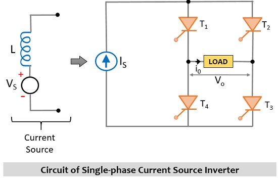
The figure given below represents the circuit representation of a single-phase current source inverter with ideal thyristors:

An assumption regarding thyristor is made over here that it possesses zero commutation time. Here we are having a voltage source in series with an inductor that provides constant current at the input terminal of the current source inverter. More simply, we have realized a high current source by using the inductance of a specific value and a limited dc voltage source.
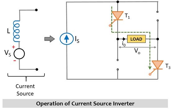
Although there are four thyristors in the configuration pair of T1-T3 and T2-T4 conduct alternatively. Initially when thyristors T1 and T3 are on then the current Is flows through the load bypassing through thyristors T1 and T3. When T1 and T3 conduct then the current flows through the load and the load current is positive and equal to the applied input current.

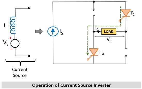
While when T2 and T4 are on then the direction of flow of load current is opposite to the former case and so the load current will be negative but equivalent to the applied input current. A noteworthy point over here is that in both cases the frequency of the obtained output waveform shows dependency on the triggering instant of the thyristors.

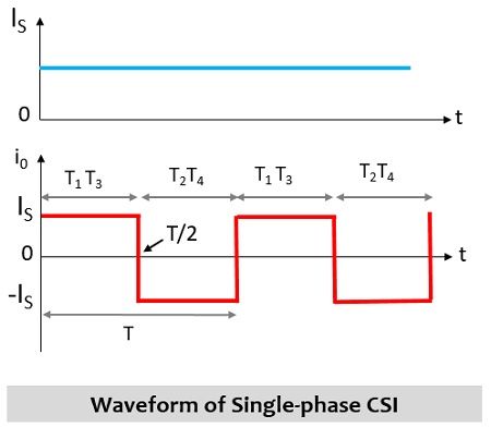
The square wave shown below represents the output of an ideal single-phase current source inverter:

Here the amplitude of the square wave obtained is equal to the magnitude of applied dc input current. It can be clearly seen from the waveform representation that the two pairs of thyristors get turned on alternatively and possess a reverse direction of flow of current.
Like the case of voltage source inverter, here also we have assumed that a pair of thyristor conducts only until the gate triggering pulse is provided to them and the moment it is removed from one pair, the triggering pulse must be immediately provided to another pair. In the above figure, it can be clearly seen that the triggering is transferred from one pair to another at instant T/2. More simply, between the instant 0 < t < T/2, T1-T3 thyristor pair is triggered while between the instant T/2 < t < T, T2-T4 thyristor pair is triggered.
If we consider the load to be capacitive then the load current will be given as:
![]()
As the supply input is invariable and so the load current iO thus the rate of change of voltage across the load must also be constant over every half cycle.
It is to be noted here that the dc input current applied to the load possesses unidirectional behavior. This means that if the power flows from source to load then the direction of current is positive while if power flows from load to source then the direction of current will be negative corresponding to the regeneration of power.
Ideally, we have shown here that a proper square wave pulse is obtained at the output. However, in the case of practical implementation, this is not actually possible and the reason behind it is that such an instantaneous rise and fall of current is not possible to get.
Advantages
- It offers easy operation as the circuit working is controlled by controlled current source i.e., the combination of current limited voltage source serially connected to the large inductance.
- The circuit is designed in a way that it can handle large voltage spikes at the time of commutation.
- The four-quadrant operation can be achieved without the need for extra power usage.
Disadvantages
- An unstable performance is noticed at light load and high-frequency operation.
- The commutation of the thyristor in the circuit shows dependency on the load current which limits the operating frequency.
Applications of Current Source Inverter
The various applications of CSI are as follows:
- It is used for speed control of ac motors.
- Induction heating
- UPS units
- Plasma generators
- Switching devices
- Synchronous motor starting
- Lagging VAr compensation
This is all about the current source inverter.
Leave a Reply