Thyristor Controlled Reactor abbreviated as TCR is a device used in power systems that offers fast reactive power and voltage limiting characteristics to the lightly loaded system. It majorly deals with controlling the temporary overvoltage condition and voltage collapse condition when there is an increase in transient stability and a decrease in system oscillations.
A TCR typically has two inverse thyristors connected in parallel configuration along with a reactance in series with them.
Introduction
Being associated with the field of electronics, thyristor controlled reactors have shown a major increase in their utilization in power systems in these developing years. TCR exhibit complete power electronics structure thus, the flow of non-sinusoidal quantities within the system, may result in resonance.
When AC systems are considered then, the magnetic field within the circuit is produced as a result of reactive power. In such a system, each individual component either generates or consumes power i.e., from generation, distribution to transmission and load.
The reactance of the circuit which is a component of impedance of a branch of ac circuit along with resistance contributes to its reactive power. The reactance can be inductive or capacitive in nature. Generally, loads are inductive in nature thus requires lagging reactive power.
A thyristor switched reactor (TSR) operates similar to TCR but unlike TCR, a TSR has a capacitor in place of an inductive reactor.
TCR Module
We have already discussed that a typical TCR is composed of an inductive reactor serially connected with two parallel bidirectional (inverse) thyristor as shown below:
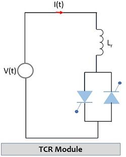
The fundamental operation of TCR is the controlling of reactive power by firing angle control of the two thyristors in the configuration. Hence, here the controlling element is the thyristor while the controlled element is the reactor. Here the two inverse thyristors conduct alternatively for the two halves of the supply frequency.
During the operation, the input provided to the thyristor valve is delayed considering the reference for the same peak of the applied voltage of each supply half input cycle.
This is clearly shown below: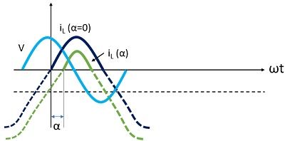
Here the voltage across the reactor leads the current by 90°. So, when a firing angle of 90° is provided then this will result in maximum current across the reactor. Furthermore, when the firing angle of 180° is provided then this will result in zero reactor current.
The range for firing angle, denoted by α is kept between 90° to 180° as this range facilitates the variation in current from zero to its highest value in reference to the crest of the applied voltage.
System Modelling of Thyristor Controlled Reactor
The system modelling of any electronic circuit is an implementation of the model as a microprocessor-based system. A thyristor controlled reactor model with system modelling possesses switching of inductor bank incorporating microprocessor.
The major components of the system are:
- Supply source
- Zero crossing detector
- Microcontroller
- Display
- Inductor Bank
- SCR
The figure below represents the block diagram of a system for improving power factor by the use of thyristor controlled reactor: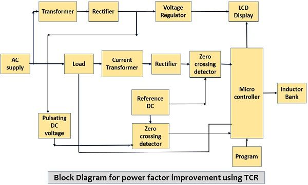
The microcontroller and other peripheral devices of the system are excited by the dc power supply. Initially, an ac supply voltage is given to a bridge rectifier which changes the applied ac input into pulsating dc. This dc signal is fed to a comparator unit which produces a digital voltage signal. In order to determine the power factor, voltage and current in digital form are provided to the microcontroller.
Therefore, the ac current signal is also changed into a digital signal similar to that of the voltage signal. Once this is done then the digital form of current and voltage signal is fed to the microcontroller unit via a zero-crossing detector. When the signals reach the microcontroller then it checks for the time difference existing between the zero crossings of current and voltage. This difference value corresponds to the range of existence of the power factor.
The microcontroller forms the connection with the LCD display unit so that the difference output can be displayed on the screen. In between the microcontroller and two inverted thyristors, there exists an optoisolator that gives electrical isolation between the two devices. So, according to the difference value, the microcontroller provides a signal to the optoisolator that turns on the bidirectional SCRs by using light energy.
It is to be noted here that a dark unit is used to enclose the isolator assembly where the source and sensor are in front of each other. The necessary inductors are connected in parallel to the load and in this way power factor can be improvised.
Stability and Harmonics
Due to either rise in load demand or a varying system state, there arises an uncontrollable increase or decrease in voltage that results in making the system unstable. This instability is mainly because the power system fails to provide the required reactive power.
To compensate for this, along with TCR, a static VAR compensator is also used. However, in some conditions, the presence of a compensator leads to an unstable power system. Also, the presence of harmonic components may result in resonance within the system leading to high distortion.
Hence, to overcome the occurrence of undesirable harmonics the operation of the circuit must be carefully done. When stability analysis of power systems is done then one gets to know the occurrence of unstable conditions under resonance.
It is to be noted here that with proper analysis, the operating point and parameter values can be determined, this also includes the determination of instability because of non-linear loads.
Leave a Reply