A small amount of dc or ac voltage is required to charge the battery. Thus, to charge any battery, suppose ac input is required then initially the input ac signal must be limited, then filtered for the removal of noise and regulated so that the voltage achieved after doing this can be used to charge the battery.
However, not only this, after the battery gets fully charged, the circuit must get turned off so that no further unwanted charging takes place.
A battery charger acts as a source for controlling and protecting the substation circuits under normal operating condition. Forming a battery charger using SCR has turned out to be a great advantage with reference to today’s time.
Need for Battery Charger relative to Power Electronics?
The need for low power battery charger systems has shown a considerable increase over time due to the fact that the use of portable appliances and communication equipment is rapidly increasing with time. And so, charging mobile devices has emerged as a challenge and to deal with this challenge, battery chargers are used.
Now, you must be thinking about how a battery charger can supply power to a battery.
In general, a battery charger supplies the electric current to the battery so that the cells within the battery can store the energy which is getting passed through it. For a battery, there are basically two types of charging modes.
The first is fast charging, which is applied to new or unused batteries. While the other is floating charging, which is applied to in-service batteries where providing supply to the load is necessary for compensation of the small charge which the battery losses during its service period.
SCR based Battery Charger
An SCR-based battery charger makes use of the switching principle of the thyristor in order to get the specific output. The circuit includes a transformer, rectifier, and control circuit as its major elements.
As we have already discussed in the beginning that a small amount of ac or dc input voltage is needed for the purpose of charging the battery. So, the elements of the circuit help to provide the desired voltage to charge the battery.
Working of Battery Charger circuit using SCR
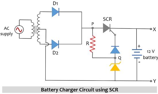
The figure below represents the circuit of a battery charger incorporating an SCR:
Here, an ac voltage signal of value 230 V, 50 Hz is applied as input and the load is a 12 V battery that is required to be charged.
Following are the circuit elements:
- AC supply
- Step down transformer
- Rectifier circuit
- SCR
- Zener diode as a voltage regulator
- Battery to be charged
Let us now understand how the above-given circuit operates.
So, initially, 230 V ac supply is provided to the step-down transformer which converts the high voltage given at the input of the primary winding into a low voltage which is obtained at the output of the secondary winding. So, here the voltage obtained at the other side of the transformer is 15V with respect to neutral.
From the circuit, it is clearly shown that the transformer forms connection with the rectifier circuit, hence the output of the transformer will be provided to the rectifier circuit. As we have an ac input signal, so let us understand how the rectifier circuit operates when the two halves of the ac signal are applied.
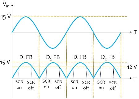
Initially, when the positive half of the ac input signal is applied then the diode D1 in the above-given configuration will be forward biased and will conduct however, D2 will be in reverse biased condition thus will not conduct. Conversely, when the negative half of ac input is applied then D1 will not conduct but D2 will be in conducting state, this is clearly shown in the waveform representation given below:

So, the rectifier circuit will provide rectified output i.e., the dc voltage at terminal P.
Here we have used a Zener diode with breakdown voltage of 10 V as a voltage regulator to regulate the voltage level of the circuit. Therefore, terminal Q will be at 10 V due to the presence of the Zener diode.
As the terminal voltage at P which is nothing but the rectified voltage is comparatively more than at terminal Q thus, this makes the SCR forward biased, allowing it to conduct and due to this current will start flowing through the load i.e., the 12 V battery. And we have already discussed in the beginning that when current flows through the battery then the cells present within it stores the energy. In this way, the battery gets charged.
However, in case, the rectified voltage is less than that of terminal voltage at Q then automatically SCR will come in a reverse-biased state, getting it turned off and no flow of current through the battery will take place further.
Thus, we can say that here the SCR is acting as a switch that controls the voltage fed to the battery. Now, the question arises, once the battery gets fully charged how the circuit will operate.
So, basically what happens within the circuit is as the rectified voltage here is 15 V, so once the battery gets fully charged (suppose it reaches 14.5 V) then the remaining value of the voltage at terminal P will be insufficient to cause further conduction through the SCR because now the rectified voltage will be less than the voltage at terminal Q. This will not allow current to reach the battery further and resultantly the charging circuit will get deactivated.
Basically, this comparison between rectified voltage and the charging potential is made using a comparator circuit. Once the charging potential falls below a certain value then the charging circuit will automatically get activated and again the charging of the battery will take place.
It is to be noted here that the value of the breakdown voltage of the Zener diode and the transformer in the circuit depends on the charging potential of the battery. Thus, the potential at which the battery will be charged will decide the value of these two circuit parameters.
Drawbacks of Battery charger circuit using SCR
- This charging is a quite time taking process.
- The rectifier circuit for ac to dc conversion, do not remove ac ripples as the filter circuit is absent here.
- The process of charging and discharging is slow due to the presence of a half-wave rectifier.
- This is only suitable for charging the batteries with a low to medium ampere-hour rating.
This is all about a battery charging circuit using SCR.
Leave a Reply