Definition: A modulation technique in which the amplitude of the pulsed carrier signal is changed according to the amplitude of the message signal is known as Pulse Amplitude Modulation (PAM).
Simply put, the transmission of data takes place by the variation of the amplitude of pulse according to the modulating signal.
Basics of PAM
The technique does not show much variation in comparison to continuous wave modulation. The only difference is that the carrier in the pulse modulation technique is not continuous in nature rather it is a rectangular pulse train.
Amplitude modulation of pulsed signal is accomplished by the sampling of analog modulating signal. The sampling of the signal is basically done either by natural sampling method or by flat top sampling.
It is to be noted in case of PAM, that flat top sampling is widely used and is more popular than natural sampling. This is so because, at the time of signal transmission the channel noise introduces some form of distortion in it, that can be easily eliminated in case of flat tops.
As against when natural sampling is done in case of PAM signals, then the top of the pulses varies according to the modulating signal. So, in this case, the elimination of noise component from the sampled signal becomes somewhat difficult at the time of detection.
At the same time, natural sampling is a bit complex process as compared to flat top sampling.
Hence, flat top sampling is preferred in pulse amplitude modulation.
Block diagram of PAM generator
The figure below shows the block diagram of a PAM generator
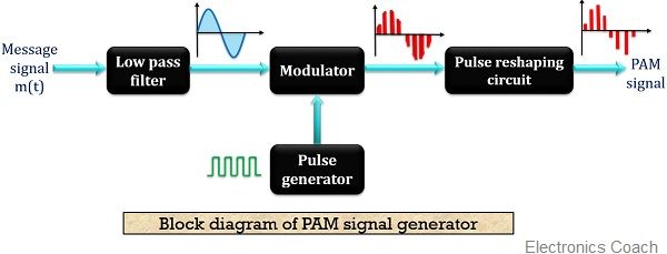
As we can see it consist of a low pass filter, a modulator along with a train generator and a pulse reshaping circuit.
Here the modulating signal is given to the low pass filter in order to band limit the message signal.
The LPF at the beginning is placed in order to avoid aliasing of the samples. The LPF passes only the low-frequency component of the signal and eliminates the high-frequency signal component. The output of LPF is then provided to a modulator, where it gets mixed with the rectangular pulse train.
Basically, the pulsed carrier gets modulated by the message signal here. The rectangular carrier pulse is generated by the pulse generator circuit.
The modulator generates a pulse amplitude modulated signal. The sampled pulses can be achieved either by natural or flat top sampling. The output of the modulator is provided to the pulse reshaping circuit. This basically shapes the pulses so that it can be easily detected at the receiver.
As we have already discussed why flat top sampling is preferred over natural sampling. Regeneration of flat-top pulses by the repeater is somewhat easier in case of long distance signal transmission.
Circuit diagram for PAM signal generation
Let us move further and have a look at the circuit diagram of a PAM signal generator.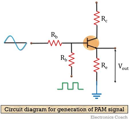
Here Rb, Re and Rc denote base resistor, emitter resistor and collector resistor and Vcc is the supply voltage. The transistor employed in the circuit is responsible for the desired pulsed signal.
The circuit is also known as emitter follower as the output is received from the emitter terminal of the transistor.
The rectangular pulse is applied to the transistor along with the message signal. When the peak of the pulse is high, it causes the transistor to operate in the saturation region. Thus, it behaves as a short circuit, allowing the analog signal to reach the output.
However, in case of the low peak of the rectangular pulse, the transistor operates in the cut-off region. Resultantly, it starts behaving as an open circuit and blocks the signal transmission.
In this way, a pulse amplitude modulated signal is transmitted.
The waveform diagram shown below will provide you with a better idea about the processing of the generator circuit.
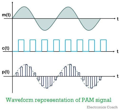
Here as we can see the first image represents the analog message signal and the next one shows the pulsed carrier wave that is to be modulated. The last figure shows the PAM signal generated by the circuit.
The PAM signal in the waveform shows flat top sampling that is most preferred due to its advantages. However, in the block diagram, we have seen the modulator is performing natural sampling.
Another important aspect that is to be considered while generating and transmitting PAM signal is its bandwidth utilization. So, lets now discuss the transmission bandwidth utilized by PAM signal.
Transmission bandwidth of PAM
During pulse amplitude modulation technique, generally, τ (tau) which is pulse duration of the modulated signal is assumed to be very small as compared to the time period between two samples denoted by Ts
![]()
Consider the maximum frequency of the modulating signal m(t) to be fm, thus in correspondence to the sampling theorem
![]()
: fs is the sampling frequency,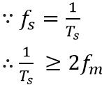
Or we can write,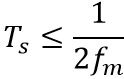
But as we already discussed,
![]()
Hence,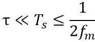
The maximum frequency of the pulse modulated signal is achieved when the ON and OFF time of the modulated pulse is same,
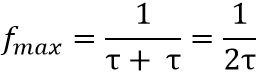
Thus, the transmission bandwidth in case of PAM signal is somewhat equal to the maximum frequency component.
So, BW ≥ fmax
However, we know,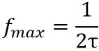
Therefore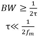
Thus,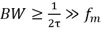
Or we can say,
![]()
Thus, the bandwidth for the transmission of the PAM signal is greater than the maximum frequency component of the message signal.
Advantages of Pulse Amplitude Modulation
- PAM is the simplest form of pulse modulation.
- Its implementation is quite easy.
Disadvantages of Pulse Amplitude Modulation
- The transmission bandwidth required is very large.
- Due to the variation in amplitude, the power required by the generating unit also varies.
- Less immune to noise due to amplitude variation.
Applications of Pulse Amplitude Modulation
It is used in LED lighting, in microcontrollers in order to produce control signals and in the Ethernet communication system.
Leave a Reply