Definition: The word dual means two. Dual converters are defined as an antiparallel arrangement of two entirely controlled converters that operate in all four quadrants of the V-I plane. It is such a device that performs two simultaneous conversions.
In a dual conversion system, the two converters out of which one acts as rectifier while another acts as inverter are connected to a common dc load. Thus is called so.
What are Converters?
A power electronic converter or simply a converter is an electrical device that makes use of components like SCRs, TRIACs, IGBTs, etc. for the purpose of controlling and converting electric power. Basically, such circuits provide power conditioning by changing one form of electrical energy into another form of electrical energy.
Power electronic converters are used to do power conversion actions. Before processing further, we must know how power electronic converters are classified. So, according to the type of function performed converters are of the following types:
- AC to DC Converter (Rectifier)
- DC to AC Converter (Inverter)
- DC to DC (Chopper)
- AC to AC (Cycloconverter)
All half-controlled converters offer single quadrant operation and help to convert ac power to dc power. In this case, the whole operation is restricted to the first quadrant, of the output current-voltage plane. While the fully controlled converters are the ones that generate direct output voltage where the current flows in one direction, operates in the first and fourth quadrant. Such converters are helpful in applications like dc torque motors.
It is to be noted here that the first quadrant operation shows rectification operation where power flows from ac to dc whereas shows inversion operation in which power flows from dc to ac network.
To have a fourth quadrant operation, two converters are connected anti-parallelly across the load. Dual Converters offer four-quadrant operation as here both voltage and current attain positive or negative polarity.
Introduction to Dual Converters
We have already discussed that semi-converters are single quadrant converters implying that, the complete range of firing angle of load voltage and current exhibit single polarity.
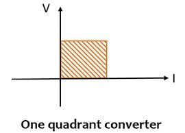
As SCRs exhibit unidirectional properties thus the direction of current cannot be reversed but the polarity of the output voltage can be reversed.
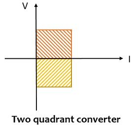
Hence, it is said that the full converter acts as a rectifier in the first quadrant where both voltage and current are positive for the value of α = 0⁰ to 90⁰. While the same acts as an inverter in the fourth quadrant where voltage and current are negative and positive respectively for the value of α between 90⁰ to 180⁰. So, basically, full converters may act as two quadrant converters. Here in the first quadrant, the flow of power is from ac source to dc load and in the fourth quadrant, the power flows from dc circuit to ac source.
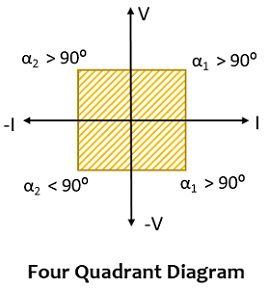
Thus, in order to have a four-quadrant operation, we use two full converters in back-to-back orientation to the load circuit. This provides an antiparallel arrangement of two full converters that give rise to dual converters.
Functional Modes of Dual Converters
There are two functional modes of dual converters namely:
- Non-circulating current mode
- Circulating current mode
In the non-circulating current mode of the dual converter, only one converter will be active at a specific time, and thus, circulating current will be absent between the converters. More simply, here only one of the converters conducts at a time while the conduction of the other one is blocked for that time. This mode of operation offers high efficiency and power factor.
In circulating current mode both the converters are active simultaneously, thus circulating current will be there in this case. Here as both the converters conduct at the same time thus, the circuit requires a current limiting reactor in the connecting terminals of the two converters. Due to the simultaneous conduction mode of the converters, the firing angle must be so adjusted that a minimal circulating current must flow through the reactor. This mode of operation offers quite a fast time response.
Ideal Dual Converter
An ideal dual converter provides such an output voltage that is free from ripples. The figure below represents the circuit of an ideal dual converter:
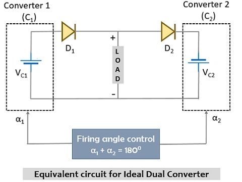
Here, VC1 and VC2 represent the magnitude of the voltage of the two converters present in the circuit. The serially connected diodes with the voltage sources are used in reference to show the unidirectional flow of current. However, the load allows the flow of current to take place in either an upward or downward direction.
The firing angles must be properly controlled here so that the average output voltage of the two converters must have the same magnitude and polarity. To attain this condition, out of the two, one converter must act as a rectifier while another as inverter.
Thus, the average output voltage for single-phase converters is given as:

: Vcm = 2Vm/π
In the normal operating condition, the two output voltages exhibit opposite polarities i.e., the two plates of converter 1 upper positive and lower negative while the two plates of converter 2 are exactly opposite. However, an assumption regarding average magnitude is made where the magnitude value is the same.
Thus, we can write the average output value as:
VC = VC1 = – VC2
On substituting the values of VC1 and VC2, we will get,

We will have,

Along with that,

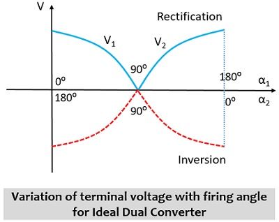
The above equation explains that the value of α1 is always 180⁰ more than α2. The figure below represents that change in output voltage for firing angles α1 and α2.
Practical Dual Converter
Recently we have discussed the ideal case, where the sum of firing angle α1 + α2 = 180⁰, this means that the converter operating as rectifier has firing angle α1 and the inverter operating with (180⁰ – α1). Although the average dc terminal voltages are considered to be equal there are chances of ac ripples at the dc terminals of the converters and due to this reason, the voltage VC1 and VC2 are out of phase practically. This gives rise to a difference in voltage of two interconnected converters that leads to cause flow of circulating current between two converters but not through the load.
So, in order to limit this circulating current, reactors are used between two converters. However, even without the use of a reactor, this circulating current can be limited by properly triggering the converters.
Here in this content, we will discuss, dual converters without circulating current.
As we have already discussed that in this mode of operation, out of the two only one converter is in operating state at a time and the overall load current is carried by it. The other converter in the circuit is not provided a firing pulse thus, is blocked in terms of conduction. The figure is shown below clearly represents the non-circulating type of dual converter:
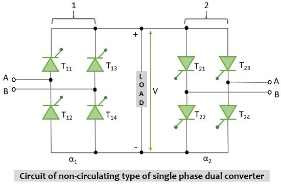
As it is a non-circulating mode thus, no reactor is present here in between the two converters. Considering C1 is in operating condition and is responsible for the load current. So, in order to stop the conduction of C1 and to activate C2, there are two ways.
One way is we can stop the firing pulse immediately while the other way is to increase the firing angle up to the maximum value and this will block the firing pulse of that converter. This leads to cause decaying of load current to 0 and at this instant, firing pulse applied to C2 will bring it to the conduction mode. Once the C2 comes into the conduction state then the current begins to flow through the load but this time the direction of flow of current is reversed. Till the time C2 is in operation, C1 will not be provided a firing pulse.
It is to be noted here that at the time of changing the conduction from one converter to another the current through the load must be reduced to zero. A delay time of around 10 to 20 sec must be there between stopping the conduction of a converter and applying the firing pulse to another converter. With this time delay, the SCRs of the active converter will get properly commutated. However, if this time delay between switching of one converter to another is skipped then this will lead to cause flow of large circulating current between the two converters as both will be in the active state.
Leave a Reply