Definition: The DC voltmeter is a device which measures the DC voltage applied to it, by moving the pointer against the perfectly calibrated scale. The calibrated scale is provided by PMMC meter.
Also, you must note here that the voltage which is to be measured is passed through the attenuator and then through the DC gain amplifier.
In order to understand the working of DC voltmeter, we may refer to the block diagram below. We can conclude from the diagram below that when the DC voltage is to be measured by DC voltmeter it is fed into attenuator, and then the output from attenuator is passed through DC coupled amplifiers.
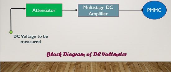
One may think that first, we are attenuating the signal and then amplifying it, what is the use of it? The answer to this question is that we need to select a particular range and this can be accomplished using an attenuator. Further, we need to intensify the signal up to the extent so that it is sufficiently high in magnitude to deflect the pointer of PMMC meter so one can easily obtain the readings of voltage.
Classification of DC Voltmeters
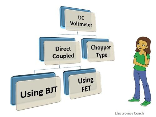
There are two types of DC voltmeters, one is Direct coupled cascaded amplifier DC voltmeter, and another is Chopper type DC voltmeter. The direct coupled cascaded amplifier DC voltmeter can be designed in two ways, first is using bipolar junction transistors(BJT). Second is using Field effect transistor (FET).
Direct Coupled Cascaded Amplifier DC voltmeter using BJT
In this, the attenuator is comprised of various resistors of suitable value. The transistors used here are PNP and NPN, both the transistors are cascaded directly so that in the circuit the usage of more number of components can be minimized. Less the components used in the circuit less will be its complexity.
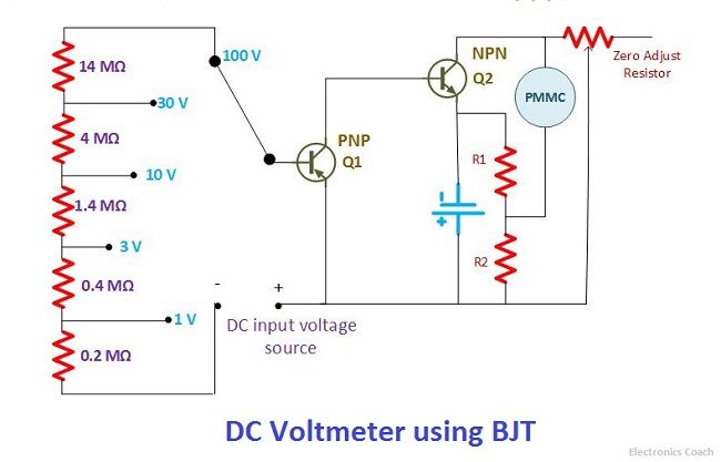
We all are aware of the fact that transistor is always termed as the current controlled device. Thus, any device which is manipulated or controlled by current always requires series connection of resistors. Thus, the resistance of 14MΩ is connected to the transistor Q1 in series.
The attenuator network will help to select voltage of a particular range. On the other hand, the network of transistors connected with each other form a high gain amplifier. The amplified voltage from the cascaded amplifier when enters the PMMC meter, the pointer in it starts showing deflection on a calibrated scale. In this way, we measure the voltage applied to it.
Advantages
- It is a low-cost device.
- It can provide the measurement of voltage in milli-volts range.
- Its sensitivity is about 200kΩ/volt.
Disadvantages
- It is suitable to operate in a particular temperature range otherwise it creates drift problems.
- There is a restriction in usage of multiple transistors for increasing gain as this will also result in drift problems.
Direct Coupled Cascaded Amplifier DC Voltmeter using FET
The Direct Coupled Amplifier using BJT results in low sensitivity and also creates a high load to the input circuit. As a consequence of which the concept of the direct coupled amplifier using FET came into existence. The most significant advantage of using FET is its high impedance.
Due to the high input impedance of FET, the input circuit connected to the DC voltmeter do not get loaded. As a consequence of this, the sensitivity offered by this circuit is much higher than the previous one.
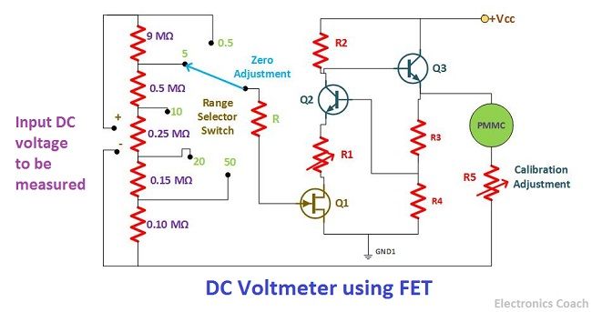
The connection architecture of DC voltmeter using FET is same as of DC voltmeter using BJT. The only difference is that FET is a voltage controlled device. Thus, the resistance network connected to the voltage controlled device is always in shunt.
Advantages
- High input impedance
- The problem of burn out of PMMC is also alleviated in this type of voltmeters. This is because whenever the input voltage exceeds its limit, the cascaded DC amplifier enters into saturation mode. Due to this, no excess current can flow through PMMC which prevents it from burning out.
- High Sensitivity
Disadvantages
- Drift problem
- It cannot measure voltage in millli-volt range as it requires high gain DC amplifier which needs more transistors to be cascaded together. But due to drift problem, we cannot cascade more transistors.
Chopper Type DC Voltmeter
The chopper type DC voltmeter was designed to overcome the drawbacks of Direct coupled amplifier DC voltmeter. The drift problem was a big issue. This drift problem can be eliminated in chopper type DC voltmeter by using capacitor along with modulators.
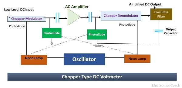
The above circuit of Chopper DC voltmeter gives us a brief idea about its working. The DC voltage which is to be measured is passed through chopper modulator which converts it into AC signal. This AC signal is then applied to the AC amplifier. The capacitors used before and after the amplifier circuit eliminates the drift issue. The chopper demodulator is used for conversion of AC signal into DC signal which is then passed through low pass filter so that any AC ripple if present; it can be eliminated.
The neon lamp gets ON and OFF with the help of oscillator for alternate half cycles. These neon lamps illuminate the photodiode which modifies the resistance of modulator and demodulator. When they are illuminated the resistance becomes low.
The DC voltage which is to be measured is obtained from low pass filter; this signal is then passed through a PMMC meter for the measurement.
Advantages
The chopper type voltmeter provides high sensitivity. Besides, the measurement range of chopper type DC voltmeter is about 10µV. Thus, it can measure voltage in micro-volt range which is not possible with direct coupled DC voltmeter.
Disadvantages
The circuit of chopper voltmeter is quite complex. In addition to this, the usage of chopper modulators and demodulators increases the cost of DC voltmeter.
Leave a Reply