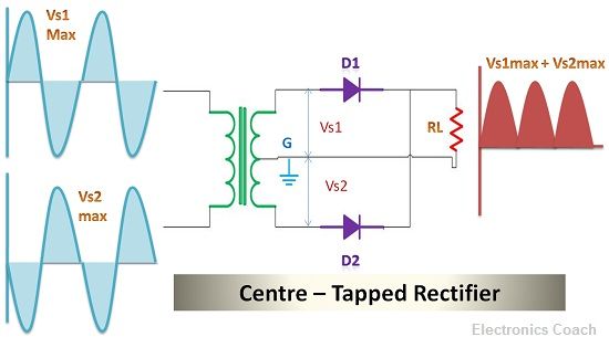
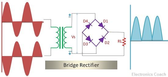
The crucial thing which differentiates Centre Tapped and Bridge Rectifier is the design architecture. Centre tapped Rectifier consists of two diodes which are connected to the centre tapped secondary winding of the transformer as well as with the load resistor. Bridge rectifier comprises of 4 diodes which are connected in the form of Wheat stone bridge and thus provide full wave rectification.
The advantage of using Bridge rectifier is that no centre tapping is required. Thus, we can eliminate the transformer from the circuit, if the step-down voltage is not required. Although, Bridge rectifier also possesses some drawbacks, among which one of the drawbacks is the voltage drop across four diodes.
Bridge Rectifier needs four diodes which makes the circuit complex, as well as the voltage drop in this scenario, will be two times more than the voltage drop in Centre-Tap Rectifier. This is because Centre-Tap rectifier includes only two diodes in its circuit.
The other significant differences can be understood with the help of comparison chart described below.
Content: Centre Tapped and Bridge Rectifier
| Parameters | Centre Tapped Rectifier | Bridge Rectifier |
|---|---|---|
| Definition | A full wave rectifier which uses two diode. | A full wave rectifier which uses four diodes connected together in the architecture resembling wheatstone bridge. |
| Peak Inverse Voltage | 2 Vs max | Vs max |
| Transformer Utilization Factor | 0.692 | 0.812 |
| Voltage Regulation | Better | Good |
| Peak Load Current | Vs max/ (RL + RF) where RL (Load resistance ) & RF (diode forward resistance) | Vs max/(RL + 2RF) |
| Transformer Requirement | Mandatory for Centre Tapping | Discretionary or not essential |
| Voltage Drop across diode | Low | High due to presence of four diode |
| Number of diodes | 2 | 4 |
| Circuit Complexity | less | More |
Definition
Centre Tapped Rectifier
In this, the anodes of the diodes are connected with Centre tapped secondary winding, and the cathodes of the diodes are connected with the load resistor. Thus, it is called Centre Tapped Rectifier. It is a type of full wave rectifier. Firstly it converts one half of the AC cycle into DC voltage and then it converts another half of AC cycle into DC voltage.

Thus, the positive half cycle of AC and negative half cycle of AC both are converted into the unidirectional voltage with the help of centre tapped rectifier. When the AC voltage is applied to the rectifier, firstly the step-down transformer lowers the magnitude of AC voltage. Then this voltage is passed through the diodes.
When the positive half of AC cycle is applied to the rectifier circuit, the diode D1 is forward biased, and diode D2 is reverse biased. This is because the top of the secondary winding is positive with respect to the bottom of the secondary winding. In this condition, D1 is forward biased, and D2 is reverse biased, and thus only D1 conducts during positive half Cycle of AC.
When the negative half Cycle of AC is applied to the rectifier circuit, the diode D1 gets reversed biased, and D2 gets forward biased. Thus only D2 conducts during the negative half cycle of AC.
In this way, the complete cycle of AC is converted into DC voltage, and the output is obtained across the load resistor. This will be the pulsating DC voltage as it also consists of AC ripples.
Bridge Rectifier
Bridge Rectifier also converts complete cycle of AC into pulsating DC, but its conversion manner is different from Centre Tapped Rectifier. All the four diodes are connected in the form of Wheatstone bridge. When AC voltage is applied to the bridge rectifier, the step-down transformer will convert it into low voltage DC voltage as it is easy to process low voltage as compared to high voltage.

When the positive cycle of AC is applied to Bridge Rectifier circuit, then diode D1 and diode D3 is forward biased while diode D2 and diode D4 is reversed biased. Thus, during the positive half cycle of AC, two diodes conduct, i.e. diode D1 and diode D3 and thus the voltage drop across load resistor is obtained. This is the pulsating DC.
During the negative half cycle of AC, the diode D1 and diode D3 is reverse biased, and diode D2 and diode D4 is forward biased. In this way for every half cycle of AC voltage two of the diodes will be forward biased and the remaining two will be reversed biased. Thus, for every half cycle, two diodes will provide conduction.
In this manner, bridge rectifier converts complete half cycle of AC into pulsating DC.
Key Differences Between Centre Tapped and Bridge Rectifier
- Centre Tapping: This is the most crucial difference between Centre tapped and Full Wave rectifier. Centre Tapped Rectifier as its name suggests is centre tapped; its secondary winding is centre tapped. While there is no centre tapping in case of the bridge rectifier.
- Count of Diodes: The centre tapped and bridge rectifier also differs in the usage of diodes. Centre tap uses only two diodes while bridge rectifier uses four diodes in its circuit. This contributes to the increment in the circuit complexity in case of the bridge rectifier.
- Peak Inverse Voltage: The magnitude of Peak Inverse Voltage of Bridge Rectifier is half of that of Centre tapped rectifier. This feature of the bridge rectifier makes it appropriate for high Voltage applications.
- Voltage Drop: The voltage drop across diodes is also considered as a crucial factor. It decides the performance of the rectifier circuit. The voltage drop across the diodes in bridge rectifier is more than the voltage drop across Centre tapped. This is because bridge rectifier consists of 4 diodes while centre tapped consists of only two diodes. This is the only drawback of using Bridge rectifier.
Conclusion
Centre Tapped and Bridge Rectifier are the types of Full wave rectifier. Both provide full wave rectification, but their working process is different. Bridge rectifier has certain advantages over centre tap rectifier. It possesses better transformer utilization factor, better voltage regulation etc. But it also has a drawback of more voltage drop as compared to centre tap as it has four diodes.
Shaji T says
The information is very useful.
thanks