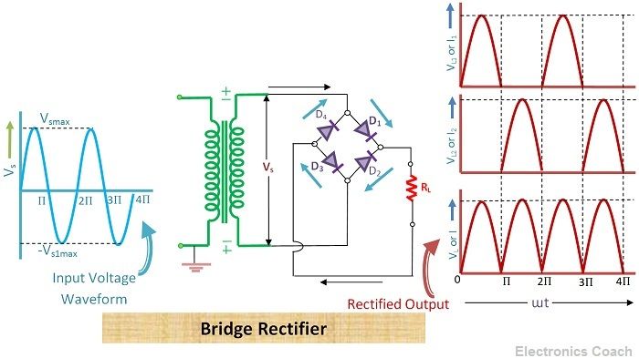
Definition: Bridge rectifier is formed by connecting four diodes in the form of a Wheatstone bridge. It also provides full wave rectification. During the first half of AC cycle, two diodes are forward biased and during the second half of AC cycle, the other two diodes become forward biased.
In this way, the rectifier provides DC output during positive AC cycle as well as during negative AC cycle.
Circuit Components of Bridge Rectifier
It consists of a step-down transformer, four diodes connected in the form of a bridge. Two of the four diodes are connected diagonally and connected to the secondary windings of the transformer and the other two diodes are connected across the load resistor.

Working of Bridge Rectifier
When the AC signal is applied to bridge rectifier the step-down transformer converts the high voltage AC signal into low voltage AC signal. The AC signal is applied to the primary winding of the transformer and through the mutual induction it is applied to secondary windings of the transformer.
Diodes operation during Positive Half of AC
When positive half of AC signal is applied to bridge rectifier, the top of the secondary winding of the transformer is positive and bottom of the secondary winding is negative. Thus, in this condition the anode terminal of diode D1 is positive and the cathode terminal of diode D3 is negative.
Therefore, diode D1 and diode D3 will be forward biased during positive half or first half of AC cycle. And diode D2 and diode D4 will be reversed biased because cathode terminal of diode D4 is connected to the terminal having positive voltage and anode terminal of diode D2 is connected to positive voltage.
Diodes operation during Negative Half of AC
When negative cycle or second half of AC signal approaches bridge rectifier, the top of the secondary winding of a transformer is negative while the bottom half of secondary winding of the transformer is positive. Thus, in this situation, the anode terminal of diode D1 is negative while cathode terminal of D3 is positive. This makes the diode D1 and D3 to operate in reversed biased condition.
During the negative half cycle of AC signal, the cathode terminal of diode D4 is negative and the anode terminal of diode D2 is positive. Thus, diode D4 and diode D2 are forward biased during the negative half of AC. While during this negative half cycle the anode terminal of diode D1 is negative and the cathode terminal of diode D3 is positive, this makes the diode D1 and D3 reverse biased.
Thus, the bridge rectifier conducts for both half of AC input signal i.e. for positive half as well as negative half. The direction of current flowing through load resistor remains same for positive half of AC cycle as well as for negative half of AC cycle.
Analysis of Bridge Rectifier
The applied voltage Vsmax appears across load resistor RL, thus peak inverse voltage (PIV) appears across the load resistor.
![]()
- Peak Current: The value of peak current of bridge rectifier can be obtained with the help instantaneous voltage applied to the rectifier circuit.
![]()
Let us consider the forward resistance of some value and reverse resistance offering infinite resistance, then we can derive the value of current through the load resistor.

The total current flowing through the load resistance RL being the sum of currents i1 and i2 is given as:-
![]()
The peak value of the magnitude of the current through the resistance RL can be obtained by below equation.

Here RF is the forward resistance and RL is the load resistance.
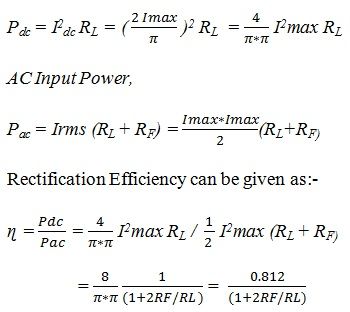
- Rectification Efficiency: The rectification efficiency can be obtained by the ratio of DC powered delivered to load and the component of AC power present in it.

Advantages of Bridge Rectifiers over Centre tap Rectifiers
- The centre tapping is not required in the secondary winding of the transformer in case of the bridge rectifier. Thus, it reduces circuit complexity. The circuit can be made more simple if we remove the transformer from the rectifier circuit in case we don’t need stepping down of voltage.
- The voltage regulation provided by bridge rectifiers is better in comparison to that of centre tap full wave rectifier.
- The transformer utilization factor in the case of the bridge rectifier is higher than that of centre tap full wave rectifier.
- The power transformer of smaller size can be used for a given power output.
Disadvantages of Bridge Rectifiers over centre tap rectifiers
- It requires four diodes for operation, thus, circuit components requirements in case of the bridge rectifier is more than that of centre tap rectifiers.
- The voltage drop across diodes increases four times than that of centre tap full wave rectifier. This creates a problem in applications where low voltages are required.
- The load resistor and supplied voltage have no common point that can be earthed.
This completes the disavantages of bridge rectifier. It is also one of the full wave rectifier but due to its bridge architecture it possess some advantages over full wave rectifier.
Leave a Reply