Definition: Clipper circuits are the circuits that clip off or removes a portion of an input signal, without causing any distortion to the remaining part of the waveform. These are also known as clippers, clipping circuits, limiters, slicers etc.
Clippers are basically wave shaping circuits that control the shape of an output waveform. It consists of linear and non-linear elements but does not contain energy storing elements.
The basic operation of a diode clipping circuits is such that, in forward biased condition, the diode allows current to pass through it, clamping the voltage. But in reverse biased condition, no any current flows through the diode, and thus voltage remains unaffected across its terminals.
Clipper circuits are basically termed as protection devices. As electronic devices are voltage sensitive and voltage of large amplitude can permanently destroy the device. So, in order to protect the device clipper circuits are used.
Usually, clippers employ resistor–diode combination in its circuitry.
Classification of Clipper circuits
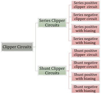
Clippers are basically classified in the following categories:
- Series positive Clipper circuit
Let’s have a look at the circuit diagram of a series positive clipper. Here, the diode is connected in series with the output thus it is named so.
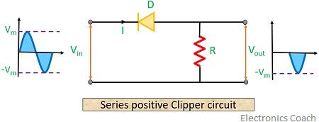
The positive half of the input waveform reverse biases the diode. Thus it acts as an open switch and all the applied input voltage drops across the diode. Resultantly providing no output voltage for positive half of the input waveform.
For the negative half of the input waveform, the diode is in the forward biased state. Thus it acts as a closed switch causing no any voltage drop at the diode.
Hence input voltage will appear across the resistor, ultimately at the output of the circuit.
- Series negative clipper circuit
The circuit below shows the figure of a series negative clipping circuit.
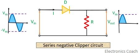
Here, during the positive half cycle of input waveform, the diode becomes forward biased, thus ensuring a closed circuit. Due to which current appears across the resistor of the circuit.
For negative half of the input waveform, the diode now becomes reverse biased acting as an open switch. This causes no current to flow through the circuit. Resultantly providing no output for negative half of the input waveform.
- Series positive clipper circuit with bias
Whenever there is a need to clip or remove a certain portion of positive half of input waveform, series positive clippers with biasing are needed.
1. The case of a Positively biased circuit:
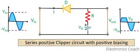
Here in the circuit shown above, we can see that the diode is in forward bias condition concerning the battery. But positive half of the input waveform puts the diode in reverse biased condition.
The diode will conduct until the supply voltage is less than the battery potential. As battery potential dominates the supply voltage, the signal appears at the positive half of output waveform. But as the supply voltage exceeds the battery potential, the diode is now reverse biased. Resultantly no further current will flow through the diode.
For the negative half cycle of the input waveform, the diode is forward biased concerning both supply voltage and battery potential. Hence, we achieve a complete negative half cycle at the output waveform.
2. The case of a Negatively biased circuit:
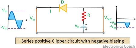
As we can see in the circuit shown above, the diode is reverse bias due to both supply voltage and battery potential. This cuts off the complete positive half of the input waveform.
But during the negative half cycle of the input waveform, the diode is in forward biased condition due to supply voltage but is reverse biased by the battery potential.
Here also initially when battery dominates the supply voltage, the diode is in reverse biased condition. But, as the supply voltage becomes greater than the battery potential, the diode will automatically come in forward biased condition. Thus, the signal starts to appear at the output.
- Series negative clipper circuits with bias
Whenever there is a need to clip or remove a certain portion of the negative half of the input waveform, then series negative clipper circuits with biasing is needed.
1. The case of a positively biased circuit:
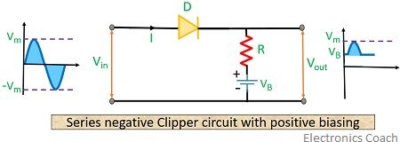
Here in the circuit, we have noticed that for the positive half of input waveform, the diode becomes forward bias. However, the battery potential causes the diode to be at the reverse biased condition.
In the beginning, the battery potential is higher than the supply voltage. Thus causing no current to flow through the circuit at that time. But when the positive half supply voltage exceeds the battery potential then diode becomes forward biased and starts conduction. Hence signal appears at the output.
The negative half cycle of the input waveform causes the diode to be reverse biased. At the same time applied battery potential reverse biases the diode. Thus no any signal is achieved at the output in such a condition.
2. The case of negatively biased circuits:
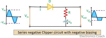
For the positive half of the input cycle, supply voltage and battery potential both cause the diode to be in forward biased condition. Thus complete output for the positive half is achieved in this case.
But in the case of the negative half cycle of the input waveform, the diode is now in reverse biased condition. At the same time due to battery potential, the diode is forward biased. So, until the battery potential is greater than the supply voltage, current flows through the circuit. Hence output is achieved.
But as the supply voltage becomes greater than the battery potential, the diode will now become reverse biased and hence conduction stops. Ultimately no any signal appears for that portion of the input waveform at the output.
- Shunt positive Clipper circuits
Now, let’s have a look at the circuit of shunt clippers shown below
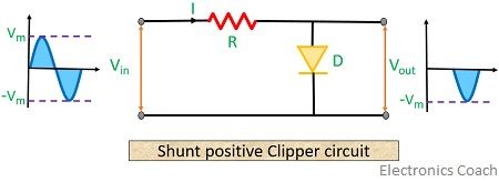
Here, the diode is connected in parallel with the load. Hence its working principle is exactly opposite to that of the shunt clippers. In shunt positive clippers, the output signal is observed only when the diode is reverse biased.
During the positive half of the input signal, the diode gets forward biased due to which the current flows through the diode. Hence, due to the parallel combination of diode and load, no current is observed at the load. Resultantly no output waveform for the positive half is achieved.
On the contrary, during the negative half of the input signal, the diode gets reverse biased. Thus no current flows through it, and the output current is observed at the load. So, for the negative half of input, the entire negative half appears at the output.
- Shunt negative Clippers circuits
Let’s have a look at the figure shown below of shunt negative clippers.
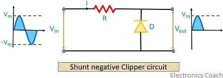
For negative shunt clippers, during the positive half of input, the diode gets reverse biased. Thus no current flows through it, and the output current is observed at the load.
Hence output signal is achieved for positive half of the input signal.
During the negative half of the input signal, the diode gets forward biased and hence no load current is achieved. Ultimately no output is observed for negative half of the input signal.
- Shunt positive clipper circuits with bias
Here, we will discuss both the cases of positive and negative biasing separately as we have done in series clipper with bias.
1. The case of positively biased circuits:
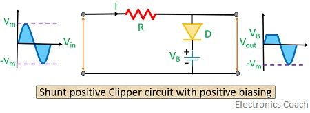
During the positive half of the input cycle, the diode gets forward biased but at the same time battery potential causes the diode to be at the reverse biased condition.
Until the battery potential is greater than the supply voltage, the reverse biased diode by the battery potential does not allow the flow of current through it. Hence current flows through load and signal is observed at the output. But when input voltage increases more than the battery potential, the diode becomes forward biased due to the supply voltage. Hence, allowing current to flow through the diode and no output is achieved.
In case of negative half of the input cycle, both battery potential and supply voltage reverse biases the diode. Hence we get a complete negative half cycle at the output.
2. The case of negatively biased circuits:
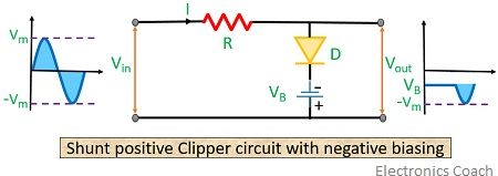
In this case, the negative half of the input cycle and the applied battery potential both causes the diode to be forward biased. Thus current flows through the diode, and no signal is observed across the output.
During the negative half of the input cycle, the diode is reverse biased due to supply voltage but is in the forward biased state due to battery potential.
So, here output will not appear at the load until battery potential is higher than the supply voltage. As the supply voltage exceeds the battery potential, the diode stops conduction due to the reverse bias condition. Hence signal appears at the output.
- Shunt negative clipper circuits with bias
Now, let’s move further and discuss the case of positive and negative biasing separately.
1. The case of positively biased circuits:
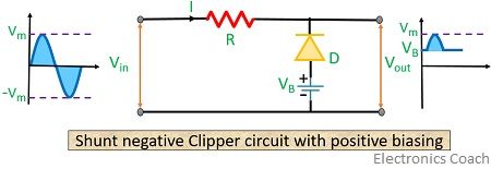
In case of positive half of the input signal, the diode gets reverse biased. However, the battery potential causes the diode to be in forward biased condition. So, until the battery potential is higher than the supply voltage, the diode conducts due to forward bias. But as the supply voltage exceeds the battery potential the conduction through diode stops. Ultimately signal appears at the output.
During the negative half of the input cycle, the diode gets forward biased because of battery potential and supply voltage. Hence, no output signal appears for the negative half of the input cycle.
2. The case of negatively biased circuits:
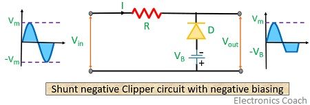
During the positive half of the input cycle, the diode gets reverse biased due to both battery potential and supply voltage. Resultantly, we have complete positive half of input signal at the output.
During the negative half of the input cycle, the diode gets forward biased due to supply voltage but is reverse biased by the battery potential. Thus, the output signal is achieved until the battery potential is higher than the supply voltage.
As the supply voltage exceeds the battery potential, the diode completely starts conduction and signal does not appear at the output.
- Dual clipper circuits
Whenever there is a need to remove a certain portion of both positive and negative half of the signal, then dual clipper circuits are used.
Let’s have a look at the circuit of dual clipper shown below-
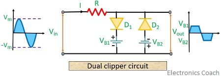
During positive half of the input cycle, diode D1 gets forward biased due to supply voltage but is in reverse bias state due to battery potential VB1. At the same time, diode D2 is in reverse bias due to both supply voltage and battery potential VB2.
Until battery voltage exceeds the supply voltage D1 will be in reverse-biased state and D2 is already in reverse bias condition. Hence signal is achieved at the output. But as the supply voltage exceeds the battery potential, it causes diode D1 to be forward biased. Hence, no any further signal for the positive half is achieved in this case.
During the negative half of the input cycle, diode D1 will be reverse biased due to both supply voltage and battery potential.
Conversely, diode D2 will be forward biased by the supply voltage but is reverse biased by the battery potential VB2.
Until the supply voltage is less than the battery potential, D2 will be in reverse-biased state and signal appears at the output in this condition. But, as the supply voltage exceeds the battery potential, D2 will be forward biased. Hence no any signal is obtained at the output.
Applications of Clipper circuits
These are used in numerous applications such as in transmission, in overvoltage protection, in the modification of input waveform, in voltage limiting etc.
Leave a Reply