The major difference between Half Adder and Full Adder is that Half Adder adds two 1-bit numbers given as input but do not add the carry obtained from previous addition while the Full Adder, along with two 1-bit numbers can also add the carry obtained from previous addition.
Half Adder and Full Adder, both are combinational logic circuit but differs in the way they process the inputs. A combinational circuit is one which does not consist of any memory elements; it comprises of only logic gates.
Another significant difference between Half Adder and Full Adder is that Half Adder consists of one EX-OR gate and one AND gate while Full Adder consists of two EX-OR gates, two AND gates and one OR Gate. If any carry is obtained in the addition process, it is given to full adder as an input, and it adds that carry along with other inputs. On the contrary, half adder does not take any carry obtained from previous addition.
The adder is the crucial digital circuit used in computers, digital processing etc. Due to the utilization of logic gates, the addition process becomes fast. Half Adder and Full Adder, both perform addition and are widely used in digital circuits for performing arithmetic functions.
Content: Half Adder and Full Adder
Comparison Chart
| Parameters | Half Adder | Full Adder |
|---|---|---|
| Definition | Half Adder is combinational logic circuit which adds two 1-bit digits. | Full Adder is a combinational circuit which adds three 1-bit digits. |
| Carry Addition | Carry generated from previous addition is not added in next step. | Carry generated from previous addition is added in the next step. |
| Hardware components | It consists of one EX-OR gate and one AND gate. | It consists of two EX-OR, two AND gate and one OR gate. |
| Applications | Calculators, computers, digital measuring devices etc. | Multiple bit addition, digital processors etc. |
Definition
Half Adder
Half Adder is a combinational logic circuit which is designed by connecting one EX-OR gate and one AND gate. It adds two one-bit numbers and generate the sum as the output.
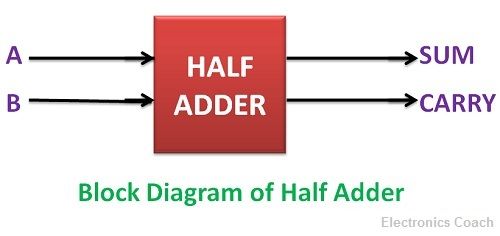
It consists of two input terminals and two output terminals, one is SUM, and the other is CARRY.
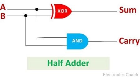
The output obtained from the EX-OR gate is the sum of the two numbers while that obtained by AND gate is the carry. But the carry obtained in one addition will not be forwarded in the other addition because there is no logic gate to process that. Thus, this is called Half Adder circuit.
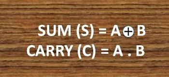
The output equation of both the gates can be written in the form of a logical operation performed by the logic gates. The sum equation will be written in the form of EX-OR operation while the carry equation in the form of AND operation.
Truth Table of Half Adder
The truth table of Half Adder represents the possible combination of input given to it and the possible outputs obtained from it. The truth table of Half Adder is given below.
| Input | Output | ||
|---|---|---|---|
| A | B | SUM | CARRY |
| 0 | 0 | 0 | 0 |
| 0 | 1 | 1 | 0 |
| 1 | 0 | 1 | 0 |
| 1 | 1 | 0 | 1 |
The output obtained from EX-OR gate will be 1 only when either the first input is 1 or the second input is 1 but not both simultaneously. The EX-OR gate output indicates the sum of the two bits starting from the least significant bit to the most significant bit.
The output obtained from AND gate will be one only when both inputs is 1, in the remaining cases the output will be 0. The output obtained from AND gate indicates the carry obtained from the addition.
Full Adder
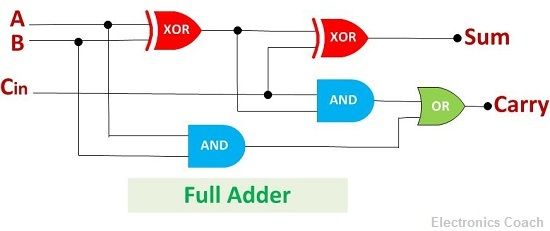
Full Adder is the circuit which consists of the circuit which consists of two EX-OR gates, two AND gates and one OR gate.
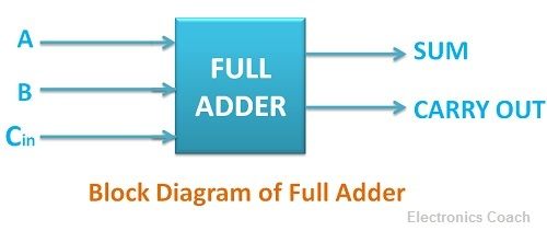
It adds three binary digits, among which two are the inputs, and one is the carry obtained from previous addition.
Like half adder, a full adder is also a combinational logic circuit, i.e. it does not have any storage element. But due to additional logic gates, it adds the previous carry and generates the complete output. Thus, it is called full adder.
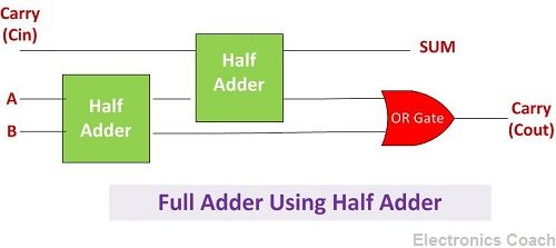
A full adder can also be designed using two half adder and one OR gate. The sum of the digits can be obtained as the output from the second Half Adder while the OR gate will generate the carry obtained after addition.
The equation of the output obtained by EX-OR gate is the sum of the binary digits. While the output obtained by AND gate is the carry obtained by addition. The equation can be written in the form of logical operation.

Truth Table of Full Adder
The truth table of the full adder is represented below. The truth table comprises of all possible combinations of three inputs given to full adder and the outputs sum and carry. It determines the binary digits obtained after addition.
| Inputs | Ouput | |||
|---|---|---|---|---|
| A | B | C | SUM | CARRY OUT |
| 0 | 0 | 0 | 0 | 0 |
| 0 | 0 | 1 | 1 | 0 |
| 0 | 1 | 0 | 1 | 0 |
| 0 | 1 | 1 | 0 | 1 |
| 1 | 0 | 0 | 1 | 0 |
| 1 | 0 | 1 | 0 | 1 |
| 1 | 1 | 0 | 0 | 1 |
| 1 | 1 | 1 | 1 | 1 |
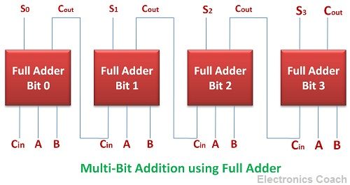
Multi-Bit Addition Circuit
We can obtain the addition of multiple bits by increasing the number of the Full adder.
Key Differences between Half Adder and Full Adder
- Half adder adds two binary digits and generates sum and carry. While full adder adds three binary digits and generates sum and carry bit.
- Another significant difference between Half Adder and Full Adder is that the carry obtained from previous addition do not add in next addition in case of half adder. On the contrary, the full adder adds the previous carry along with the current inputs.
- The hardware architecture of Half Adder and Full Adder is also different from each other. Half Adder consists of only one EX-OR gate and AND gate. While the full adder consists of two EX-OR and AND gate with one OR gate.
Similarities
- Half Adder and Full Adder, both are the combinational digital circuit. This means both the circuit does not have any memory element like sequential circuits.
- The above two combinational circuits are crucial for arithmetic operation. Both the combinational circuits provide the addition of binary numbers.
Conclusion
The Half Adder and Full Adder are the building blocks of various digital circuits such as computers, calculators, digital measuring techniques. The advantage of using Adders is that it is the part of the digital circuit. And logic gates form the backbone of the digital circuit, and they process the input very fast.
The speed of processing by logic gates is in microseconds, and we need fast computation of results in almost every application, and thus, we use adders.
Vikram kaushik says
This is very helpful site on adders. Thank you for this very much.
Muhammad Mumtaz Khan says
So amazing information