Definition: Frequency division multiplexing is a multiplexing technique in which multiple separate information signals can be transmitted over a single communication channel by occupying different frequency slots within common channel bandwidth.
FDM technique is basically used for muxing of analog signals.
Look at the figure given below to understand how multiple signals can be transmitted over a common channel.
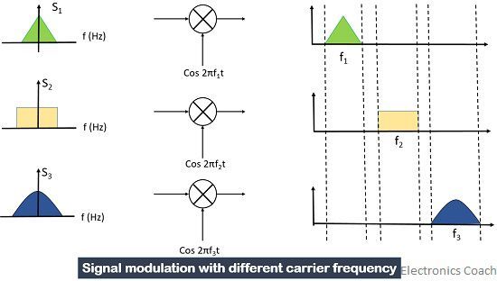
In Frequency division multiplexing simultaneous transmission of the signal takes place over a common channel in which the channel bandwidth is divided into various sub-channels. These sub-channels comprised of different frequency slots for carrying individual signal during transmission.
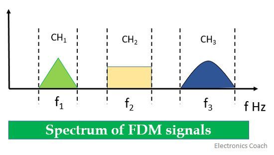
When we talk about the transmission of various signals to a long distance through FDM technique, the required bandwidth needed for transmission must also be large. Now, the question arises how can we provide multiple signals, various frequency slots under the same channel bandwidth?
The answer to the above question is modulation. The different input signal modulates different carriers having different frequencies. These signals are then mixed to form a hybrid signal for transmitting it over a single channel.
When we talk about a common communication channel the thing that first comes to our mind is overlapping of signals. But here the total available bandwidth is divided into various non-overlapping frequency bands which will carry different input signal thus preventing them from causing interference. We can use the full allotted time for transmission, the only need is the division of frequency. Sometimes this transmission during the same time interval leads to crosstalk.
FDM Transmitter Section
Now, let’s have a look at the working of the transmitter section of Frequency division multiplexer.
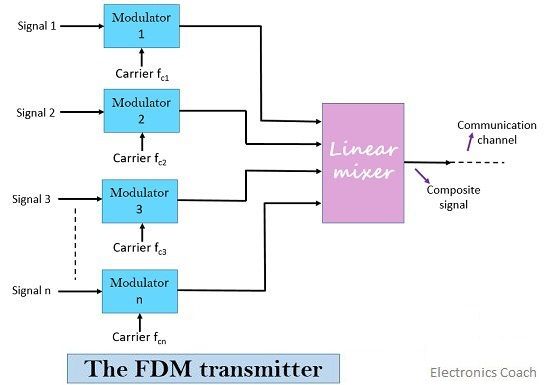
The numerous signals that are to be transmitted along a common channel modulate different carriers in the modulating section. The output of the modulator will have multiple signals of different carrier frequency.
The modulated signals are then fed to a linear mixer which is different from a normal mixer.
Linear mixer simply produces the algebraic sum of the generated modulated signals. The combined signal at the output of the mixer is then transmitted along a single channel.
FDM Receiver
Now, the receiver section will have a composite signal that was transmitted by the linear mixer over a channel.
This composite signal is then fed to different filters mainly BPF each having a centre frequency corresponding to the carrier frequency.
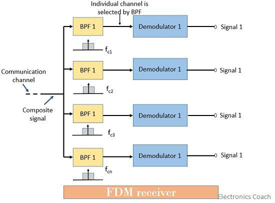
The BPF passes the channel information without any distortion. BPF rejects signals of all other frequencies and accepts the signal of the desired centre frequency.
Further, the signals after being processed by the BPF goes to individual demodulator section where demodulation of the signals takes place to separate modulating signal from that of the carrier signal.
So, after demodulation, we can have separate signals that were actually transmitted over the same channel.
Multiplexing Hierarchy in FDM
In FDM hierarchy different levels of the multiplexer are shown in a combined manner. The various levels are shown below:
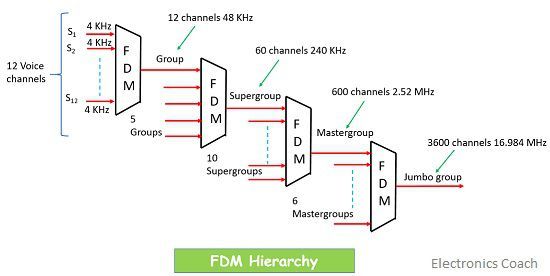
- Level 1 denotes the “basic group” in which 12 voice channels are multiplexed together.
- Level 2 is the “supergroup” in which 5 basic groups are multiplexed together and as each basic group has 12 voice channels so in level 2 we have 60 voice channels.
- Level 3 is the “master group” in which 10 supergroups are mixed together and have up to 600 voice channels.
- Level 4 denotes the “jumbo group” which has 6 multiplexed master groups and up to 3600 voice channels.
What is a Basic Group?
A group that has 12 multiplexed voice channels. These voice channel modulates the carrier signal in the frequency range from 60 KHz to 108 KHz and is spaced at 4 kHz from each other.
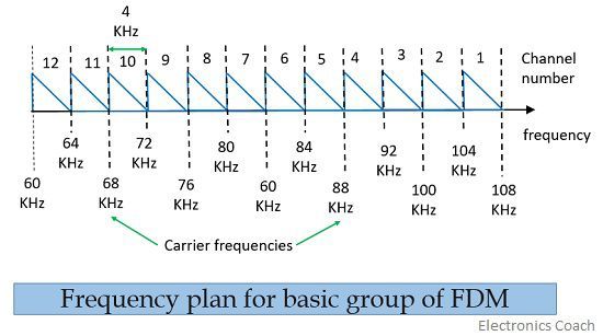
We use SSB modulation technique so that we can save the bandwidth.
The best application we can have is in television and radio systems where multiple signals are transmitted over a single channel with different frequency slots.
Telephone system also suggests us a very good example of FDM technique.
Let’s discuss the application of FDM in the telephone system.
In this, the 12 voice channel modulates different carriers and then these modulated carriers are added in a mixer.
The carrier frequency is modulated in the range from 4 KHz to 108 KHz range and the spacing provided to them is of 4 KHz each. The output of balanced modulator gives upper sideband and lower sideband.
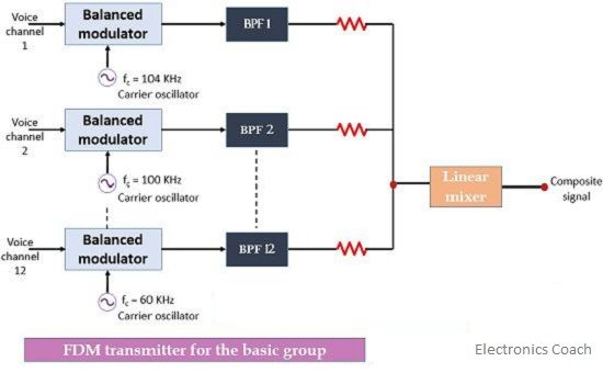
The upper sidebands are selected by using bandpass filter(BPF). Now the 12 USB signals are added by a linear mixer to produce a combined signal.
At the receiver end, the BPF demodulators are used for demodulating the received signal so that we can have the actually transmitted signals at the output of the receiver.
Advantages:
- It is a synchronization-free technique as we don’t need synchronization between transmitter and receiver.
- It facilitates the transmission of a large number of signals simultaneously.
- FDM demodulation is easy.
Disadvantages:
- The channel bandwidth required is large.
- It can result in crosstalk as several signals are transmitted during the same time interval.
- It can cause intermodulation distortion.
To prevent the interference caused during FDM we use guard bands which is of range 0 to 4KHz and these are the unused portion of the spectrum.
Mahi sharma says
GOOD WORK 👍👍👍
Sreenivas says
Very nice dealing with topics. Thank you, Ma’am.