Definition: Frequency Mixer is a non-linear device. It generates a number of frequencies on the application of two different frequencies at the input of the mixer. It is the core process in RF technology and design.
Here, the input frequency gets converted into different frequency components so as to process the signals more effectively.
It is clearly shown below that out of the two provided frequencies one is the input signal while the other is the local oscillator signal.
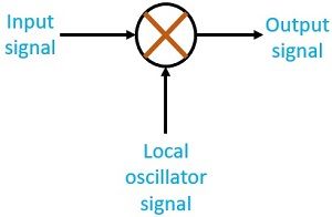
Let’s have a look at the Frequency Mixer shown schematically in the figure-
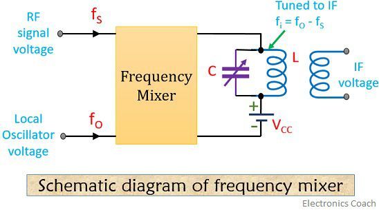
As we can see, two inputs are applied to the frequency mixer. One is an incoming RF signal voltage of frequency fS and the other is a local oscillator voltage having frequency fO.
Frequency Mixer is said to be a non-linear device as it has non-linear dynamic characteristics. This is the reason why the two input voltages after heterodyning within the mixer produce an output current. This output contains frequency component fS, fO, mfO ± nfS where m and n are integers.
A tuned circuit outside the mixer is employed that produces difference frequency component. This difference frequency is known as intermediate frequency.
It is given as –
fi = fO – fS
So, we can say that every RF signal voltage is reduced to an intermediate frequency. Its standard value is 455 KHz for AM.
In order to have, intermediate frequency, the frequency of local oscillator must be greater than that of the signal frequency. It should vary in such a way so as to maintain difference frequency at the output.
To have a detailed explanation about intermediate frequency refer to our previous article Superheterodyne receiver.
Types of Frequency Mixer
1. Self-excited mixer – The mixer circuits that uses FET or MOSFET are known as the self-excited mixer.
- BJT Mixer – Let’s have look at the circuit diagram of BJT mixer:-
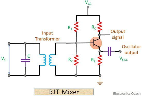 Here, the input signal is Vi = Vm1 sin ωL t and
the local oscillator signal is VOSC = Vm2 sin ωH t
Here, Vi is at a lower frequency as compared to the local oscillator signal. The low-frequency input signal is applied to the base and the oscillator signal is given at the unbypassed emitter of the transistor.
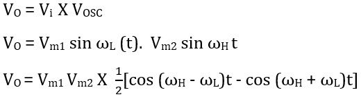
Thus, we can say, the output has two frequency component.
A sum frequency (ωH + ωL) and difference frequency (ωH – ωL). This difference in frequency is known as Intermediate frequency. A frequency selection network employed at the output of mixer selects intermediate frequency.
- FET Mixer- The active device in case of FET mixer is an N-channel JFET. The figure below shows the circuit diagram of JFET mixer –
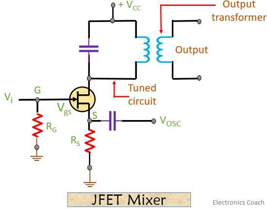
As we can see the low-frequency input signal Vi is applied at the gate terminal and the oscillator signal is applied to the source. The drain current ID is related to gate-source voltage VGS. This gate to source voltage depends on the difference between input and oscillator voltage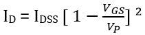 : IDSS = maximum drain current
VGS = gate to source voltage
VP = pinch off voltage
But,
VGS = VG – VS
VGS = Vi – VOSC = V1 sin ω1t – V2 sin ω2t
Advantages of FET Mixer
- FET mixers are less noisy as compared to BJT.
- In case of high-frequency applications, JFET mixers are used. As JFET is a fast device.
2. Separately excited mixer– The mixer circuits including diodes are known as the separately excited mixers.
- Balanced Mixer – Let’s us consider the figure of the balanced mixer using diodes shown below-
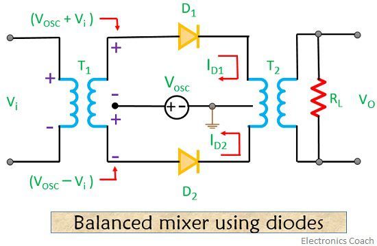 Here, the signal VOSC from the oscillator is applied to anodes of both the diodes. This is done via two halves of secondary windings of transformer T1. The polarity of input signal voltage decides the polarity of the voltage that is induced in the secondary winding of T1.
The input voltage to the two diodes D1 and D2 in case of the positive half cycle of Vi is given as:-
VD1 = VOSC + Vi
VD2 = VOSC – Vi
So, the input voltage through D1 will be higher as compared to D2.
Resultantly the current ID1 through diode D1 will be more as compared to D2.
ID1 > ID2
The voltage at transformer T2 i.e., the output voltage is proportional to the net primary current. This net primary current is given as ( ID1 – ID2 )
Hence, VO∝ ID1 – ID2
Similarly, in case of the negative half cycle, the current through D2 will be more as compared to D1. This is so because the input to D2 will now be higher as compared to D1.Due to this, the net current of T2 is negative and the induced voltage will also be negative.
- Diode ring Mixer- The figure below shows the circuit diagram of a diode ring mixer-
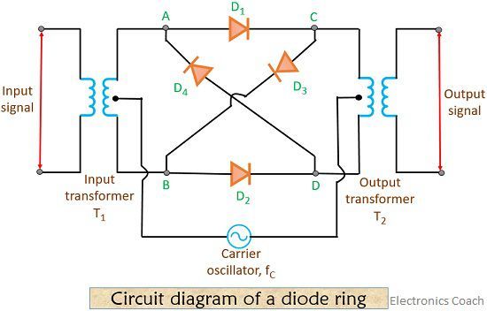
As we have already discussed earlier that oscillator signal voltage is much higher than that of the input signal.
So, here also conduction of diode will depend upon the polarity of the oscillator signal.
In case of positive half of oscillator voltage, diode D1 and D2 will be forward biased and in case of a negative half cycle, diodes D3 and D4 will become forward biased.
So, the conduction of diodes at a given instant, the secondary induced voltage of T1 will be connected in the similar manner as shown or in an inverted manner across primary of T2.
Applications of Frequency Mixer
- It is used for frequency translation. One major application is in Superheterodyne receiver.
- It is used in phase-locked loop as it helps to detect the phase difference between two signals.
During mixing of different frequency signals, the incoming RF signals suffer a reduction and get reduced to a standard frequency value known as intermediate frequency.
Leave a Reply