Hydraulic Actuator is the type of actuator that utilizes the hydraulic pressure as input in order to provide excitation to the plant (controlled process) of the control system. The controller provides the control signal to the actuator that hydraulically applies the equivalent signal to the plant in order to have the desired output in controlled operations.
The hydraulic systems possess an operating pressure range between 1 to 35 Mega Pascals.
These are widely used in closed-loop control systems whenever there is a need for high speed as well as large force operations.
What is an Actuator in Control System?
A device used in a control system that uses the output of the controller to provide a control signal to the plant to get the desired output is known as an actuator. An actuator is a crucial unit of a control system because the control signal from the controller signifies the change needed for converting the achieved output into the desired one.
We have already discussed this while discussing the operation of the closed-loop control system that the feedback unit provides a part of the achieved signal back at the input side of the system. Here the reference input is compared with the signal achieved at the output in order to check the existing difference between the two.
The difference in the value of reference input and achieved output signifies the error signal. This error signal is provided to the controller that generates the control signal that corresponds to the error signal.
This control signal is provided to the actuator and the actuator further changes it into the type of signal which can drive the plant(motor) involved in the operation.
This implies that the control signal from the controller drives the actuator of the control system. Further, the actuator unit excites the plant of the system. And this way, the controlled output is generated.
Actuators are generally classified into two categories:
- Hydraulic Actuators
- Pneumatic Actuators
Here in this article, we will discuss hydraulic actuators. So, let us proceed.
Operating Principle of Hydraulic Actuator System
Hydraulic actuator system uses the concept proposed by Pascal generally known as Pascal’s Law or Pascal’s Principle.
Pascal’s Law states that the pressure applied at a specific point to a confined fluid in a container is transmitted equally in all the directions within the fluid as well as the walls of the container without any loss.
Suppose, if pressure P is applied to an area A, then the resultant force due to an applied pressure will be:
F = P * A
Now, if a certain force F is applied in a smaller area to have pressure P in a confined fluid, then the force produced on a larger area as a result of it can be comparatively larger than the force created by the pressure.
In this way, the applied pressure at a certain point is used to generate very large forces and this principle is utilized by various hydraulic systems.
Hydraulic Fluid
The fluid utilized in the hydraulic system must be necessarily incompressible in nature. This is so because the incompressible nature of the fluid will facilitate the transmission of power to all portion of the fluid instantaneously. These systems use petroleum-based oils or some non-inflammable synthetic oils.
The use of such oils also provides lubrication to the moving parts of the hydraulic system thereby reducing the losses due to friction along with this it facilitates cooling of the components that reduces the chances of fire hazards in case of extreme heat generation during operation.
Mostly petroleum oils are used by these systems as these offers very low compressibility. Also, this oil acts as a seal to prevent leakage from any of the components.
Working of Hydraulic Actuator
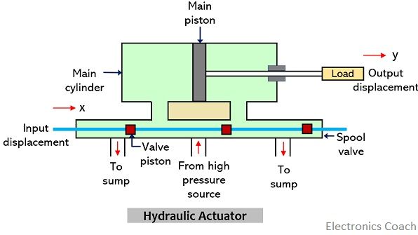
The figure below represents the schematic representation of the hydraulic actuator:
The major component of the unit is pilot valve also known as spool valve and main cylinder (or power cylinder).
It operates in a way that difference in pressure created at the two regions of the main cylinder leads to the occurrence of translational motion of the piston. Let us see the functioning of the hydraulic linear actuator.
As we have already mentioned that the main cylinder has two regions. These two regions are obtained by dividing the main cylinder with a main piston. Thus, there are two chambers of the main cylinder.
The rate with which the fluid flows inside the cylinder is controlled by the spool valve. The spool valve has 4 ports and each port is connected to a different part of the system.
Two separate ports are connected to the fluid supply and drain region respectively. While the other two ports are connected separately to the two chambers of the main cylinder.
Initially, the spool is present at the neutral position say x = 0 and at this position, there will be no flow of fluid inside the main cylinder. The assembly of the hydraulic actuator is such that the load will move according to the fluid flow.
Thus, when input displacement, x is 0 then the output displacement y will also be 0.
As soon as a certain input displacement is provided, then the spool moves towards the right. The movement of spool towards the right causes the fluid from the high-pressure source to move towards the left chamber of the main cylinder.
Thus, the pressure on the left chamber of the cylinder rises comparatively more than that present on the right chamber. This results in the generation of accelerating force that causes movement of the load.
In this way, the direction in which fluid flows corresponds to the direction in which the load moves. This acts as power amplification as discussed in operating principle because the force supplied to displace the valve is comparatively very small than the force generated that actually displaces the load.
Hence, in this way hydraulic actuators operate.
Leave a Reply