Definition: The actuators that are designed to operate on compressible fluid generally air, is known as Pneumatic Actuator. The Pneumatic actuators use the pressurized air as input and change it into mechanical motion.
More specifically, pneumatic actuators are devices that change the pressure obtained by compressing the air into mechanical energy.
Introduction
We know that actuators are the devices employed in the control system that acts on the control signal received from the controller and generate an equivalent signal that drives the plant of the system.
This is so because it is not necessary that every time the signal produced by the controller can drive the plant involved. This is the reason actuators are used.
Actuators are of two types:
- Hydraulic and
- Pneumatic Actuator
What are Hydraulic Actuators?
In the previous section, we have discussed hydraulic actuators that use oil as the fluid which is incompressible in nature to provide the desired mechanical response.
The hydraulic actuator operates on the principle of Pascal’s Law by the use of which the applied pressure is converted into extremely large force. And this force further drives the system.
Anyway, here in this article we will have a discussion on Pneumatic Actuators.
Operating Principle
Pneumatic technology is associated with the study of the behaviour of compressed air. Basically, the system based on pneumatic technique utilizes air as the medium for their operation.
A pneumatic actuator operates in a way that it converts the pressurized air applied to it into displacement. The two major units of these actuators are piston and diaphragm.
In this type of actuator, these two units create the motive power from the supplied air. More simply, air power is used to create motion.
Pneumatic Actuator is generally of two types:
- Linear and
- Rotatory
The above classification of pneumatic actuators is based on the type of motion produced by it. If the device generates linear motion then it is said to be linear pneumatic actuator. While, if the conversion from air to motion is rotational in nature then it is said to be rotatory pneumatic actuator.
Working of Pneumatic Actuator
In the previous action, we have discussed that a pneumatic actuator changes the energy from a pressurized fluid into desired mechanical action or motion.
Let us see the major components of the pneumatic system:
- Flow Control Valve
- Diaphragm
- Compressor
- Storage Reservoir
- Spring
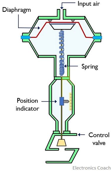
The figure shown below represents the pneumatic actuator:
As we know that here the fluid energy is changed into mechanical energy for driving the system. The functioning of the system shown above is such that the fresh air is compressed by the compressor and is stored in the storage reservoir.
The direction, rate of flow along with the pressure of the fluid is controlled by a flow control valve. The spring unit manages to carry the air from one location to another and provides return stroke to the piston.
- Initially, in the absence of any supplied air, the control valve remains open and the diaphragm is pulled upwards by the action of the spring.
However, when the air is drawn from the atmosphere then it is filtered by a filter and is provided to the compressor. The compressor now compresses the air that causes an increase in the pressure level.
It is to be noted here that with the increase in pressure level of the air, its temperature also increases. So, to maintain the temperature to a moderate range, air coolers are used.
- Now, the pressurized air is stored in a storage reservoir so that the pressure level can be maintained. Furthermore, the pressurized air inside the system applies force on the diaphragm of the actuator. When the force due to pressurized air overcomes the force of the spring that keeps the diaphragm at the top then the this causes downward movement of the diaphragm thereby closing the control valve.
With the increase in the pressure of supply air, the diaphragm continuously moves in the downward direction and this completely closes the control valve at a certain point of time.
While once this supply pressure decreases, then the force that is applied by the spring on the diaphragm overcomes the force due to supplied pressure. This causes motion in the upward direction of the diaphragm thereby opening the control valve.
- It is to be noted here that the position of the control valve depends on the air pressure. Thus, opening and closing of the control valve is related to the movement of the diaphragm so with the air pressure.
We know the actuators are present after a controller that provides a control signal for the desired action to take place. According to the obtained control signal, the air pressure varies and this simultaneously varies the position of the control valve.
In this way, the assembly inside the actuator operates according to the received control signal and drives the process.
Advantages
- Pneumatic actuators offer operation up to a wide temperature range generally, 0 to 200 °C.
- It offers ease of construction and requires less maintenance.
- These actuators are fire and explosion-proof.
- Pneumatic actuators are less costly and low weight devices.
Disadvantages
- The output power delivered by the pneumatic actuator is lesser than the hydraulic actuator.
- The internal machine parts are not lubricated due to the use of air as the fluid.
- The accuracy of the produced output is somewhat less in low-velocity operations.
- These work efficiently only when used for specific applications.
Thus, the above discussion about pneumatic actuators concludes that their use in the control system provides the control signal to the plant so as to get the desired output.
The position of the control valve with the movement of the diaphragm corresponds to the mechanical motion produced by it.
Leave a Reply