The major difference between RC and RL circuits is that the RC circuit stores energy in the form of the electric field while the RL circuit stores energy in the form of magnetic field.
The RC circuit is formed by connecting a resistance in series with the capacitor and a battery source is provided to charge the capacitor. The RL Circuit is formed by connecting a resistance with an inductor and a battery source is provided to supply the current to the inductor.
Another significant difference between RC and RL circuits is that RC circuit initially offers zero resistance to the current flowing through it and when the capacitor is fully charged, it offers infinite resistance to the current. While the RL Circuit initially opposes the current flowing through it but when the steady state is reached it offers zero resistance to the current across the coil.
There exist some more crucial difference between RC and RL circuits; we will discuss all those with the help of comparison chart. But before that let’s have a look at the contents of this article.
Topic: RC and RL Circuits
| Parameters | RC Circuit | RL circuit |
|---|---|---|
| Definition | The RC circuit is a series connection of resistance and capacitance, this circuit stores energy in the form of electric field. | The RL circuit is a series combination of resistance and inductance which stores energy in the form of magnetic energy. |
| Power Dissipation | High Power Dissipation | Low Power Dissipation |
| Filtering of Signals | Appropriate for filtering of low power signals. | Appropriate for filtering of high power signals. |
| Size and Cost | Small in size, light weight and cheap. | Inductors are large in size and thus RL circuits are bulky and expensive. |
| Noise | RC circuit generated low noise or negligible noise. | RL circuit consists of inductors which creates magnetic field which creates hysteresis and noise in the circuit. |
Definition
RC Circuit (Resistance – Capacitance Circuit)
The RC circuit involves the charging of a capacitor through the external supplied voltage. Initially, when the switch is closed, the resistance offered by the RC circuit is zero. This is because the capacitor is uncharged, after sometime when the capacitor is fully charged then as no more voltage is required the resistance offered by the RC circuit is infinite.
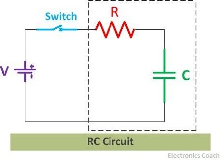
The variation of the charge with externally applied voltage is given in the diagram below.
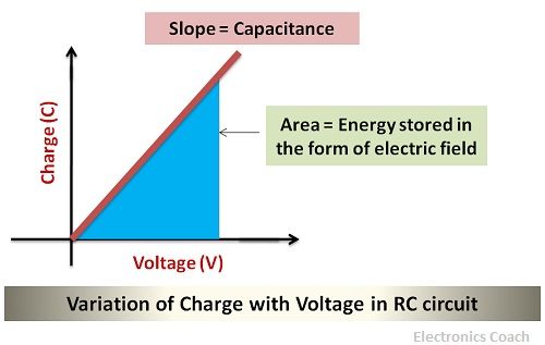
It is clear from the above diagram that the charge increases with the increase in voltage. In order to understand capacitance, we need to analyze the diagram above. The slope of the above graph represents the value of capacitance.
The area covered in the above graph represents the energy stored in the form of the electric field. This is because the parallel plates of the capacitor store the charge and it gets converted into electrostatic energy.
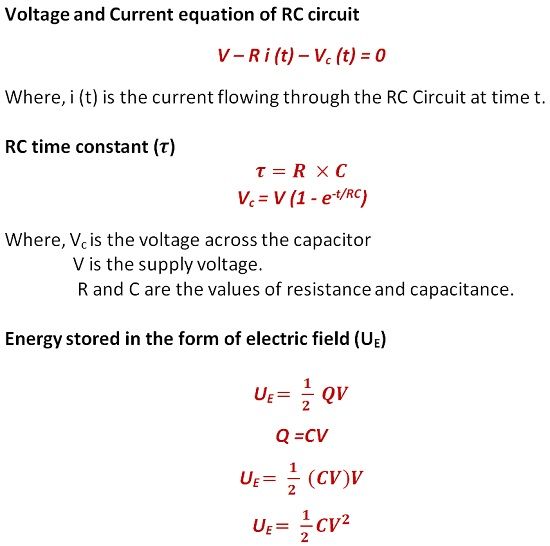
Mathematically, the current flowing through the RC circuit can be calculated with the help of Kirchhoff’s law of voltage and current. The energy stored in form of the electric field can be written in terms of charge and voltage. With the help of below equation, you can develop a better understanding of RC circuit.
RL Circuit (Resistance – Inductance Circuit)
The RL circuit consists of resistance and inductance connected in series with a battery source. The current from the voltage source experiences infinite resistance initially when the switch is closed. As soon as the RL circuit reaches to steady state, the resistance offered by inductor coil begins to decrease and at a point, the value of resistance of RL circuit becomes zero.
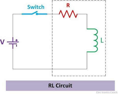
The flux linking with the inductor coil creates the magnetic field around it. Moreover, the flux varies with the current flowing through the coil. The variation of flux with the current is shown below with the help of a graph.
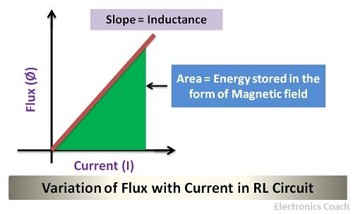
The slope of the graph depicts the value of inductance while the area covered by the graph determines the energy stored in the form of magnetic field.
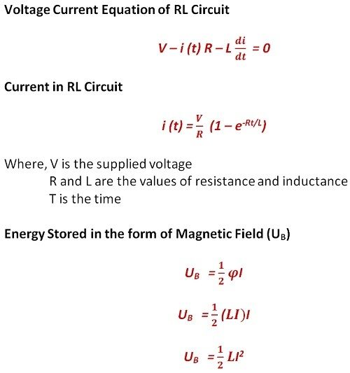
To understand it more clearly, you may refer to the equation shown below. These equations show the relationship between current, inductance and externally supplied voltage with the help of Kirchhoff’s law. The energy which is stored in the form of the magnetic field can be expressed in terms of flux and current.
Key Differences between RC and RL Circuit
- The RC and RL circuit, both stores energy, but the RC circuit stores energy in the form of an electric field. While RL circuit stores energy in the form of magnetic field.
- The RC circuits are economical as capacitors are cheap and abundantly available while inductors are costly which makes RL circuit expensive.
- The inductors possess a wider tolerance ratings in comparison with resistors, thus RL circuit has high tolerance values.
- The inductor generates the magnetic field which creates noise in the circuit. This leads to poor performance of RL circuit when the noise signal becomes high. The problem of noise can be mitigated by using RC circuit as the capacitor does not generate the magnetic field.
Conclusion
The RL and RC circuit are the backbone of various electronic circuits. Both of these has its advantages and disadvantages; it depends on the application that which circuit is to be used.
If you are dealing with low power application, then RC circuit is appropriate as it is of low cost. But if your application requires high power then RL circuit should be used. The RL circuits are more complex and heavy than RC circuit . This is because inductors are heavy and are not found abundantly but they are created by wounding metallic wire in the iron core.
Husnain Farooq says
very interesting