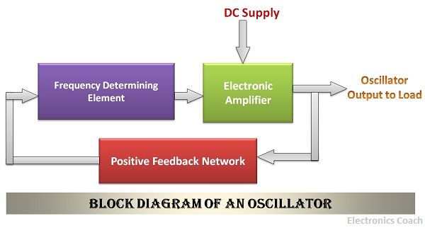
Definition: Oscillator is a circuit which utilizes positive feedback amplifier to generate sinusoidal waveforms of fixed amplitude and frequency. It is the major source of power in electrical and electronic instruments. The amplifier provided with the positive feedback can generate the sinusoidal signal even in the absence of any input. These signals are termed as oscillations, and hence the device is known as an oscillator.
The positive feedback here implies the addition of some part of the signal from the output with the input signal voltage. This is allowed to pass through the amplifier circuit. The amplifier passes it with the input signal coming from the source. The amplifier does nothing other than adding the signal coming from the feedback path and the input signal. Thus, continuous oscillations are generated, and at a time a stage is reached when without any input signal the oscillator circuit generates waveforms.
The oscillator does not generate the energy of its own, to generate oscillation but uses DC source to convert the DC power into AC. Therefore it is also termed as an inverter which is the opposite of rectifier.
The oscillators are available in wide range of frequencies. According to the frequency of the oscillation, the oscillators are named accordingly. The range of some of the oscillators are given in the table below.
| Type of Oscillators | Approximate Range |
|---|---|
| Audio-frequency Oscillators | 20 Hz - 20 kHz |
| Radio-Frequency Oscillators | 20 kHz - 30 MHz |
| Very low-frequency Oscillators | 15 - 100 kHz |
| Low frequency Oscillators | 100 - 500 kHz |
| Broadcast Oscillators | 500 kHz - 1.5 MHz |
| Video - Frequency Oscillators | 0 - 5 MHz |
| High - Frequency Oscillators | 1.5 - 30 MHz |
| Very high - frequency Oscillators | 30 - 300 MHz |
| Ultra - high frequency Oscillators | 300 - 3000 MHz |
| Microwave Oscillators | Beyond 3 GHz (3000 MHz) |
Oscillatory Circuit
The circuit of the oscillator is termed as the tank circuit. It consists of the capacitor and an inductor. The capacitor is already charged and connected to an inductor with the switch between them. When the switch is open, nothing will happen.
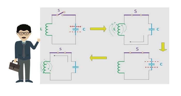
When the switch is closed the charge stored by the capacitor will start discharging, and the electrons will start flowing in the circuit. Please note that the direction of flow of current in the circuit will be opposite to the direction of flow of electrons.
When the current flows in the circuit, the current will pass from inductor due to which magnetic field is generated. The magnetic field is generated because the current flowing in the circuit will create the flux which in result create the magnetic field.
Due to the magnetic fields around inductor, the energy is stored in the inductor in the form of magnetic field. When the capacitor is fully discharged the current flowing in the circuit will begin to cease. Now the magnetic field which has been created around the inductor will generate emf.
This is because of Lenz law which states the magnetic field created will oppose the cause which has created it. The emf thus induced will cause current to flow again in the LC circuit. As a result of induced emf the charge will flow and as a consequence of this induced emf, the charge will be stored in the capacitor. The capacitor will store the energy in the form of the electrostatic field.
This process of charging and discharging of the capacitor and inductor will continue forever unless the process is terminated externally. In this way, the capacitor will charge at a time, and then inductor will charge at another point of time. Therefore, oscillations will generate continuously.
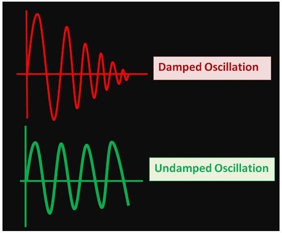
However, if you are thinking about the amplitude oscillations, so there is a twist in that. Generally, the oscillations generated by an oscillator are damped oscillation. Ideally, it is considered that the oscillation generated by the oscillator is undamped and continuous sinusoidal but practically, this is not possible.
This happens because there exist some losses in the resistor and inductor due to which the oscillation loses its energy, and therefore the amplitude starts diminishing. The losses in a resistor are different than that of losses in the inductor. The resistor suffers from dielectric loss while inductor suffers from radiation and resistive loss.
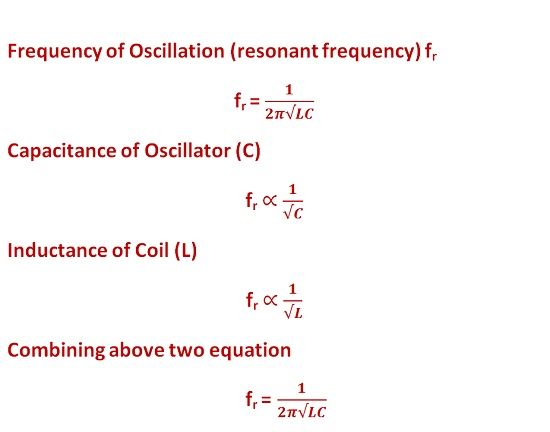
Frequency of the Oscillator Circuit
The frequency of the Oscillator circuit is called as the resonant frequency. The resonant frequency is expressed in terms of inductance and capacitance. The resonant frequency is inversely proportional to capacitance as well as inductance.
Principle of Oscillator and Barkhausen Criterion
The principle of the oscillator is that when the feedback factor or the loop gain is one, then the overall gain of the oscillator circuit will be infinite.
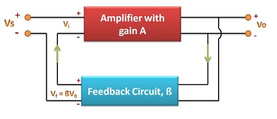
This implies that even when there is no input then also the oscillator will continue to generate the output.
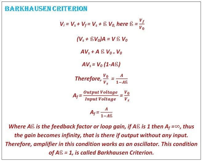
This is the essential condition for the amplifier to acts as the feedback. To summarize the condition, we can say that an amplifier which uses positive feedback and which possess infinite overall gain is termed as the oscillator circuit.
Advantages of Oscillator Circuit
- Economical: The oscillators are cheap in cost which makes them economical.
- Portable: The Oscillator uses DC source to convert the unidirectional current into the bidirectional current. Due to the usage of DC source, it does not require any moving component to generate energy. Thus, it makes it less bulky and more portable.
- Low Noise: As oscillators do not use any moving part for conversion of energy thus it makes less noise during operation.
- Varying Frequencies: The frequency of oscillation can be modified by the appropriate usage of DC source and its magnitude. Therefore, the oscillators are available with wide range of frequencies.
These are some of the crucial advantages of an oscillator circuit which makes it suitable for application as a power source in AC circuits. The oscillators can be classified in two categories that are harmonic oscillators and relaxation oscillators. Harmonic Oscillators generate sinusoidal waveforms while relaxation oscillators generate non-sinusoidal waveforms.
Leave a Reply