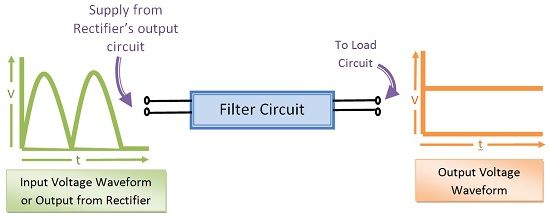
Definition: The filter circuit is necessary for smoothing of the voltage obtained by the rectifier. The obtained DC voltage contains AC components. These AC components are called ripples. The filter circuit is needed to remove the ripples from DC output voltage so that the output voltage across the load will be regulated.
Significance of Filter Circuit
Filter Circuit is connected between the load and output of rectifier circuit. If this filter circuit is not connected between the rectifier and load the performance of the system will be poor because the output voltage will consist of AC ripples.
If the pulsating DC is used for charging of a battery, it will create issues because here the need is to simply charge a battery. On the contrary, if this pulsating DC is used for radio or tape recorder it will create a problem. The 50 or 100 Hz pulsating DC signal will lead to poor performance of the device.
Thus, it is crucial to use smooth and steady DC output voltage for such applications. And in order to smooth the pulsating signal, we need a filter circuit.
Components involved in filter Circuit
A filter circuit comprises of generally inductor and capacitor. The inductor allows DC only to pass through it and capacitor allows AC only to pass through it. Thus, a circuit formed by the combination of inductors and capacitors can effectively filter the signal according to the application.
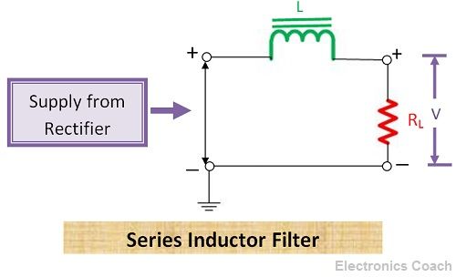
Series Inductor Filter
In series inductor filter the inductor is connected in series with the rectifier output and the load resistor. Thus, it is called series inductor filter. The property of an inductor to block AC and provides zero resistance to DC is used in filtering circuit. When the value of DC output from the rectifier is more than the average value then the rectifier store the excess current in the form of magnetic energy.
When the value of DC from the rectifier is less than the average value then the inductor release the stored magnetic energy in order to balance the effect of the low value of DC. In this way series inductor filter maintains the regulated DC supply. Moreover, inductor blocks the AC ripples present in the output voltage of rectifier; thus, smooth DC signal can be obtained.
Mathematical Expression of output DC voltage and Ripple factor
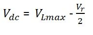
Let the voltage across load resistor RL be VL. Thus, the value of VL is given by the below equation.
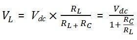
Where Vdc is the DC output voltage output of full wave rectifier, and Rc is the resistance of inductor coil. The value of resistance of inductor coil is much less than the value of resistance of load resistor. Expanding the term of VL with the help of Fourier series we get the below equation.
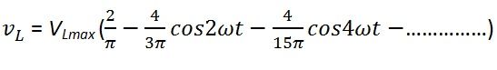
The value of resistance of inductor coil or more precisely the value of reactance of inductor coil is much less than the resistance of load resistor RL. Thus, the entire DC voltage will appear across the load resistor and the value of DC voltage across RL will be equal to VLmax.
The reactance of inductor coil or choke coil increases with the increase of frequency thus at higher frequencies the voltage will be negligible. Thus, the AC voltage is considered significant up to second harmonics only i.e. VLmax.
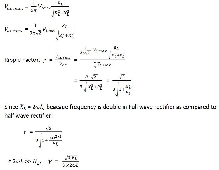
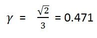
When the value of load resistance is infinite, then the output circuit will behave as an open circuit, in this case, ripple factor can be given by the below equation.
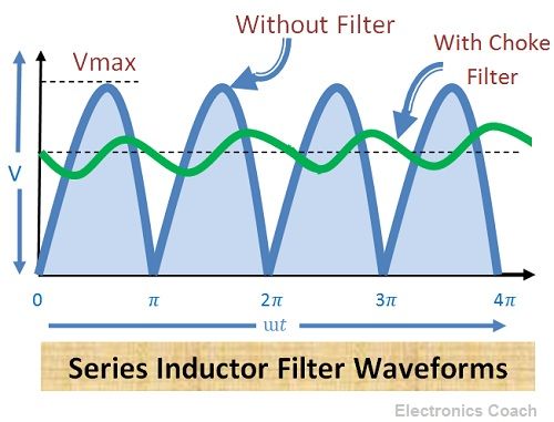
Waveforms of Series Inductor Filter
The waveform of series inductor filter is given in the below diagram. It can be seen that waveforms without filter consist of AC ripples while the waveform with filter is regulated.
Shunt Capacitor Filter
The Shunt capacitor filters comprise of capacitor along with the load resistor. In this, the capacitor is connected in parallel with respect to the output of rectifier circuit and also in parallel with the load resistor. During conduction, the capacitor starts charging and stores energy in the form of the electrostatic field. The capacitor will charge to its peak value because the charging time constant is almost zero.
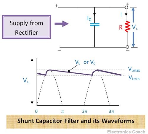
During non-conduction, the capacitor will discharge through the load resistor. Thus, in this way, the capacitor will maintain constant output voltage and provide the regulated output. The shunt capacitor filters use the property of capacitor which blocks DC and provides low resistance to AC. Thus, AC ripples can bypass through the capacitor.
If the value of capacitance of the capacitor is high, then it will offer very low impedance to AC and extremely high impedance to DC. Thus, the AC ripples in the DC output voltage gets bypassed through parallel capacitor circuit, and DC voltage is obtained across the load resistor.
Mathematical Expression of Ripple factor
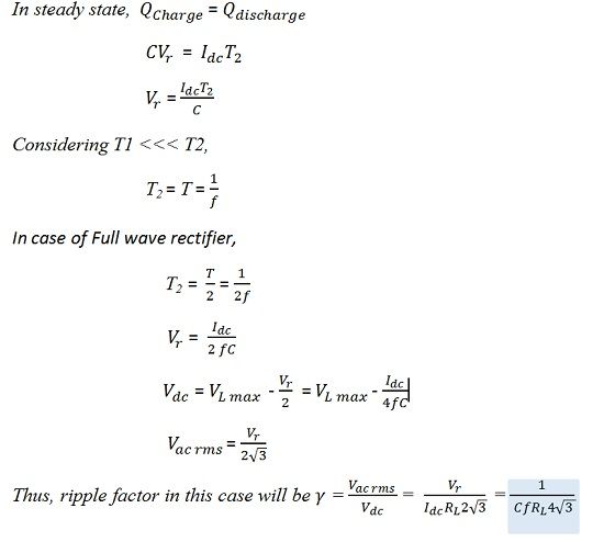
Let Vr be the ripple component of voltage, and Vdc is the DC value of Voltage and voltage across the load resistor RL be VL max.
Let the charging duration be T1, and discharging duration be T2. Then, total charge lost during non-conduction or discharge will be given as:-
![]()
The value of charge Q = CVr.
With the help of mathematical equation, you can easily understand the working of the filter circuit. Besides, its cut-off frequency can also be determined with the help of these equations.
San says
Very good data and explanation
Remigius Rweyemamu Scarion says
Thanks a lot for your recommendable job. I have obtained a concept I didn’t have before. I sincerely appreciate your work is so useful!