Definition: Function Generator is basically a signal generator that produces different types of waveforms at the output. It has the ability to produce waveforms such as sine wave, square wave, a triangular wave, sawtooth wave etc. An adjustable frequency range is provided by the function generator which is in the range of some Hz to several 100KHz.
There exist various function generators that have the ability to produce two different waveforms simultaneously by using two different output terminals.
Function Generator is a versatile instrument as an extensive variety of frequencies and waveforms are produced by it. The various waveforms generated by the function generator are suitable for various applications. It provides adjustment of wave shape, frequency, magnitude and offset but requires a load connected before adjustment.
This instrument not only varies the characteristics of the waveform but also has the capability to add a dc offset to the signal. Mostly these are only able to operate at low frequency but some costly models can also be operated at the higher frequency.
As we have discussed earlier that it can generate 2 different waveforms simultaneously at the two different terminals. So, it can be a useful feature as different output are required for particular applications. It provides another important feature as they have the capability of phase locking to an external source.
This implies that a function generator can phase lock another function generator and the output of both can be displaced in phase.
Block Diagram and Working of Function Generator
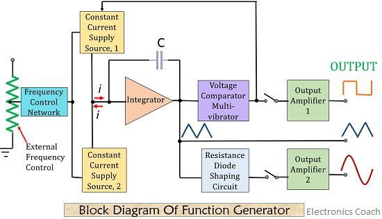
The figure below shows the block diagram of the function generator-

A frequency control network used here whose frequency is controlled by the variation in the magnitude of current. The current sources 1 and 2 drives the integrator.
By using Function Generator, we can have a wide variety of waveforms whose frequency changes from 0.01 Hz to 100 KHz. The two current sources are regulated by the frequency controlled voltage.
A constant current is supplied to the integrator by current supply source 1. Due to this, the voltage of the integrator rises linearly with respect to time. This linear rise is according to the output signal voltage equation:![]() Any increase or decrease in the current will resultantly increase or decrease the slope of the voltage at the output and thus controls the frequency.
Any increase or decrease in the current will resultantly increase or decrease the slope of the voltage at the output and thus controls the frequency.
The Voltage Comparator Multi-vibrator present here cause variation in the state of the integrator output voltage at a previously determined maximum level. Due to this change of state, the current supply from source 1 cuts off and switches to supply source 2.
A reverse current is supplied to the integrator by current source 2. This reverse current cause drops in the output of integrator linearly with time. As before this time also, when the output attains a predetermined level, the comparator again changes its state and switches to current supply source 1.
Thus we will have a triangular wave at the output of the integrator whose frequency depends on current by the supply sources as we can see in the block diagram shown above. A square wave signal is obtained at the output of the comparator.
The resistance diode network employed in the circuit changes the slope of that triangular wave with distortion less than 1%. The output amplifier thus helps to provide two waves at the output simultaneously. This captured signal can be displayed by using an oscilloscope.
Applications Of Function Generator
Function generator provides a wide variety of applications such as in RF-related operations, automotive applications, in educational, medical and industrial fields etc.
ICL 8083 Function Generator
Intersil manufactured IC 8083 known as ICL 8083 has a tremendous capability of generating various types of waveforms. It uses 3 separate output terminals over a frequency range from 0.0001 Hz to 1 MHz
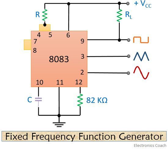
The frequency of the circuit is controlled by an external voltage and may be determined by an externally connected resistor-capacitor combination.
The 8083 is basically a relaxation oscillator that produces a triangular waveform. Voltage comparators and digital type storage devices then internally convert triangular pulses into a rectangular waveform. When there is a need to convert a triangular wave into sinusoidal wave 16 internal transistors are needed to be employed.
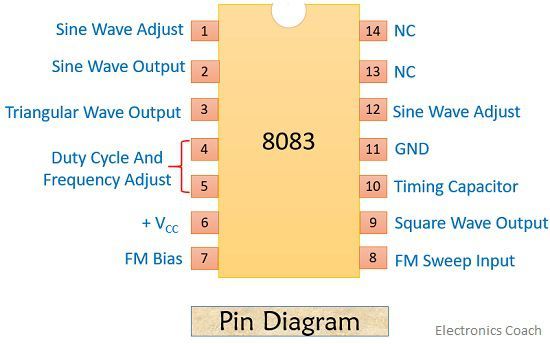
Let’s have a look at the Pin diagram of ICL 8083 shown below:

Sine Wave Adjust Pins 1 and 12:
These are used for connecting external resistors to minimize sinusoidal waveform distortion.
Duty Cycle and Frequency Adjust Pins 4 and 5:
These are used to connect external resistors with that to external capacitors C known as timing capacitor, connected to pin 10 to determine the duty cycle and frequency of the outputs.

FM Sweep Input Pin 8:
This pin is connected with an external voltage to adjust the output frequency.
NC Pins 13 and 14:
These two pins denote no connection.
So, we can conclude that a Function Generator is an electronic equipment that generates various electrical waveforms. They cover operations of both audio and RF frequencies.
Leave a Reply