Definition: The circuit that produces a linearly varying voltage or current with time is known as Time-Base Generator. It is basically a function generator that generates a sawtooth waveform of high frequency. These circuits are also known as sweep circuits. This is so because they are used to sweep the beam of electron across the screen in a horizontal direction in CRO.
Types of Time-Base Generator
These are basically of two types:
- Voltage time-base generator: It generates a voltage that varies linearly according to time and finds its application in electrostatic deflection.
- Current time-base generator: It generates linearly varying current with respect to time at the output. This current is then allowed to flow through inductor or deflection coils and used in the field of electromagnetic deflection.
Time-Base signal
A CRO basically measures or display a quantity that varies according to the time. This needs CRT spot to move with a constant velocity that resultantly requires a linearly varying voltage to be applied at the set of a deflection plate.
Now, let us have a look at the Time-base voltage waveform shown below. It is sometimes known as the sweep voltage waveform.
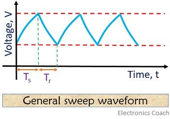
Here, we can see that the linearly varying voltage starts from a point, it can be 0 and returns to the same point after reaching the peak value.
The duration of time at which there is a linear increase in the voltage of the waveform is known as Sweep time and denoted by Ts. On the other side, the time duration required by the signal to return to its initial value is known as Restoration time or retrace time Tr.
Normally the output generated by a sweep circuit is shown above i.e., sweep voltage waveform. However, an idealised output is a sawtooth waveform that results when Tr is very small or negative with respect to Ts. That particular ideal sawtooth or ramp voltage waveform is shown below.
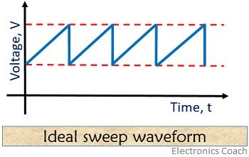
In the case of an idealised waveform, the sweep produced voltage becomes exactly linear and the retrace time is 0 that is shown in the figure above.
Errors of sweep waveform in Time-Base Generator
Practically it is not possible for a time-base generator to provide exactly linear sweep voltage. However, if we still consider that an exactly linear sweep voltage is generated, it will definitely get distorted during transmission. So there are commonly 3 different ways to express deviation from linearity.
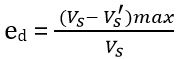
Slope or sweep speed error:
In a sweep generator, there is a need to keep sweep speed constant with time. The variation in sweep speed results in non-linearity of the slope of sweep voltage. This error is known as sweep speed error and is given as
![]()
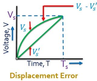
Displacement error:
It is the ratio of the maximum difference between actual and linear sweep voltage to the peak value of sweep voltage. It is given as
The figure below shows the graphical representation of the displacement error:
It holds significance in timing application and defines non-linearity of a signal.
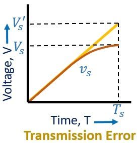
Transmission error: It is a result of passing sweep voltage through a high pass R-C network because the maximum amplitude of output deviates from the input. It is given as
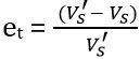
The figure below shows the transmission error in a sweep waveform:
For smaller deviation sweep voltage can be considered as the summation of linear and quadratic terms then
![]()
Methods of sweep voltage generation
It is practically not possible to obtain exact linearity in sweep voltages, thus, different methods are developed to achieve it. The methods are discussed below:
- Exponential charging: In this method, a capacitor is charged through a resistor exponentially from a voltage source up to a value which is somewhat smaller as compared to source voltage.
- Constant current charging: Here, a constant current source is used to charge the capacitor linearly.
- Miller circuit: In this method, a step is converted into a ramp waveform using an operational integrator.
- Bootstrap circuit: In this circuit, basically, a constant voltage is used across the resistor in series with a capacitor in order to maintain a constant current.
- Phantastron circuit: This circuit is a modified version of the miller circuit where pulse input is needed rather than step waveform.
- Compensating network: These are the circuits that improve the linearity of the signal but is used along with bootstrap and miller time base generator.
- Inductor circuit: Here, linear charging of the capacitor is done by using a series RLC circuit.
The most commonly used methods of sweep voltage generation among all the above is exponential charging and miller sweep and bootstrap time-base generators.
Applications of Time-base generator
- It is used in CRO for measuring and displaying time-varying quantity.
- Time base generators are used in radar system in order to obtain target range.
- These circuits are used in computer monitor and television indicators.
- Automatic controlling system and analogue to digital converters use these circuits for controlling and converting applications by time variation.
- For accurate time measurement and time modulation techniques time-base circuits find their uses.
In a time-base generator, the displacement error is less ascendant as compared to the sweep speed error.
Leave a Reply