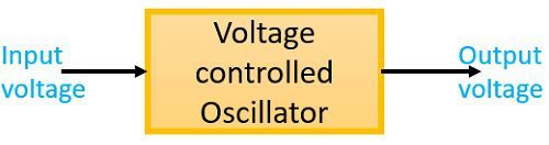
Definition: VCO is an acronym for Voltage Controlled Oscillator. It is a device that produces such an oscillating output signal whose frequency can be regulated or altered by the input dc voltage.
In other words, we can say, VCO generates an output signal having an adjustable frequency range that is controlled by the dc input voltage. It is a type of oscillator in which the output frequency obtained is the function of the input signal. Usually, the frequency of an oscillator is measured by RC time constant. However, there exist some applications where the frequency is to be controlled by the input voltage.
The output signal generated by VCO can typically be a square and triangular wave.
VCO can be in the form of either LC, crystal oscillator, RC oscillator or Multivibrator.
For RC type oscillator the frequency is given as,
Here, the frequency of the oscillator is inversely proportional to C.
In case of an LC type oscillator, the frequency is given as,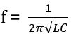
So, again there exists an inverse relationship between f and C.
Thus, any increase in the control voltage will resultantly decrease the capacitance. This decrease in capacitance will ultimately increase the frequency of the system.
Therefore, simply saying, by increasing the control voltage, oscillator frequency increases.
In a VCO, the oscillator runs at its usual frequency on applying nominal control voltage Vc. The frequency of the oscillator increases with the increase in Vc above nominal and decreases with the decrease in Vc below nominal.
So, to have variable voltage mostly, varactors are used.
VCO mainly exists in 2 categories-
- Linear VCO or Harmonics oscillator
In this type of oscillator, LC tank circuits are employed so as to provide a sinusoidal waveform. Its operation is such that the capacitance of the varactor diode is varied by the voltage across the diode.
Thus, the capacitance of LC network changes due to varactors that ultimately causes change in frequency. This category of oscillator provides much better noise frequency and temperature stability. - Relaxation Oscillator
This category of waveform generates the triangular or sawtooth waveform. This type mainly shows its applications as an Astable Multivibrator or Schmitt trigger.
Working of VCO using IC 566
As we have discussed earlier a VCO generates output whose frequency is controlled by the dc input voltage.
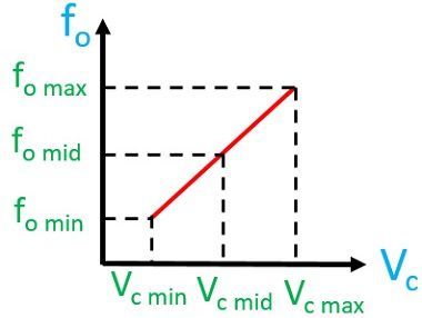
Let’s have a look at the block diagram shown below-
Here, VCO provides square wave and triangular wave at the output simultaneously as a function of dc input voltage.
As we can see, the input voltage is applied at the control terminal 5. The frequency of the oscillator is set by external resistance and capacitance R1 and C1. IC 566 has current sources shown in the figure above that are responsible for charging and discharging the external capacitance C1. And the external resistance R1 and dc input voltage decide the rate for charging and discharging.
By making use of Schmitt trigger present in the circuit, the current sources switches between charged and discharge capacitor.
The schmitt trigger provides square wave and the triangular voltage generated across the capacitor are the output that is given together through the buffer amplifier. This buffer amplifier transfers the high impedance to a low impedance output so that the output impedance of each is 50Ω.
The magnitude of the triangular wave and square wave is usually 2.4 Vpeak-to-peak and 5.4 Vpeak-to-peak.
As we can see in the below-shown diagram of the waveform-
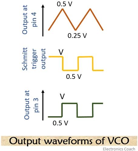
During capacitance charging when the voltage at C1 surpasses 0.5 V the output of Schmitt trigger goes low.
Now, at 0.25 V the capacitor starts discharging, due to which Schmitt trigger’s output will be high. The period of charging and discharging of Schmitt trigger are same.
The total change in the voltage of capacitor is from 0.25 V to 0.5 V i.e., ∆v = 0.25V.
As the capacitor is charged with the constant current source,

Or, 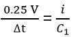
So,![]()
For, triangular waveform, the time period is ![]()
The oscillator frequency is given as-
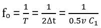
But,
Thus,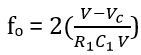
So, from the above equation we can, say the output frequency can be changed by the variation of either R1, C1 or Vc.
VCO is commonly used to convert the low-frequency signal into audio frequency range.
Working of VCO using Op-amp
The other form of VCO using Op-amp is shown below-
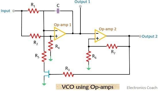
A square wave is generated at the output of the above circuit whose frequency is controlled by the input voltage.
The Op-amp at the beginning of the circuit works as an integrator. As the control voltage is applied, at the input terminal of the op-amp, due to the voltage divider arrangement only half of the control voltage is applied at the positive terminal. The voltage at the negative terminal is at the same level so as to maintain a voltage drop across R1.
The current from resistor R1 flows through MOSFET. The input voltage charges the capacitor. Thus, providing steadily rising output voltage.
Now, when MOSFET is turned OFF, the current through R1 discharges the capacitor C1. Thus we will have falling output voltage. So, we will have a triangular waveform at the output of op-amp 1.
Here, op-amp 2 works a Schmitt trigger. The output of op-amp 1 serves as the input of op-amp 2. At the output of op-amp 2, a square wave is obtained.
Applications of VCO
- These are used in function generators.
- VCO is the elemental building block of phase locked loops.
- In frequency shift keying techniques.
- In frequency modulation.
- These are used in tone generators.
VCO’s are the most commonly used electronic oscillator. But in the category of VCO, a broad range of operating frequency is provided by relaxation oscillator.
Leave a Reply