A sub-classification of forced commutation in which the device is commutated by transferring the load current of the main thyristor to another thyristor in the circuit is Class C Commutation of the Thyristor. Another name for this type of commutation is complementary commutation.
This commutation technique shows high reliability and suits operations at frequencies below 1000 Hz.
What is Commutation of Thyristor?
Commutation of Thyristor defines the process to turn the thyristor off. We have previously discussed that to turn the thyristor on along with supply input, the device necessarily requires a gate pulse in order to trigger the thyristor. This means at the time of turning on, the gate pulse acts as a switch and once the device begins to conduct then even on removing the gate signal, the device continues to conduct.
As there is no such switch to turn off a thyristor that is in conducting state thus external circuitry is needed that helps in turning the device off. The various methods that help in turning off the thyristor are known as thyristor commutation techniques.
Previously we have discussed class A and class B commutation techniques.
In class A commutation, the current through the thyristor reaches to 0 value by making use of commutating components (L and C). The inductor basically opposes the change in current through the circuit thus after a certain period of time, the current automatically reaches 0. While in class B commutation, a resonant LC circuit is utilized.
Circuit of Class C Commutation
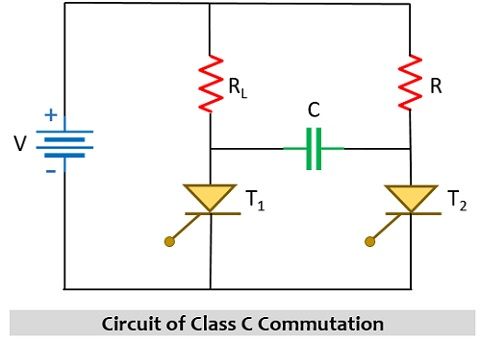
This commutation technique makes use of two thyristors, one is main and another is auxiliary (complimentary), this is clearly shown below:

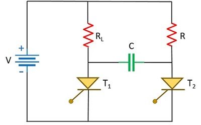
Here the main thyristor is denoted as T1 while the complementary thyristor is T2. The main thyristor is serially connected with the load while the auxiliary one is parallelly connected with the main thyristor.
It is given the name complementary commutation due to the reason that the two thyristors in the circuit get on alternatively. This means that to turn the thyristor off, the auxiliary thyristor is triggered whereas to turn off the auxiliary thyristor, T1 is triggered.
We have already discussed that forced type of commutation makes use of dc supply. So, let us see, how the class C commutation circuit operates on providing dc input signal.
Working of Class C Commutation
To understand the operation of class c commutation, there are three modes of operation.

Both the SCRs of the circuit carry load current but not simultaneously. Let us understand each mode of operation separately.
Mode 0: This mode of operation corresponds to the initial state of the circuit when both the thyristors are in off state and so the voltage across the capacitor is also 0.
This means, T1 = off; T2 = off; VC = 0
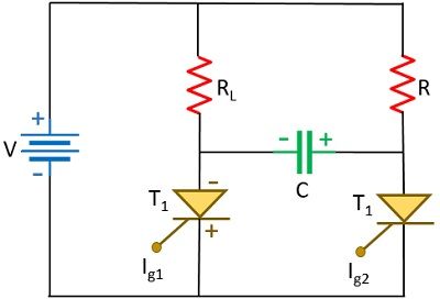
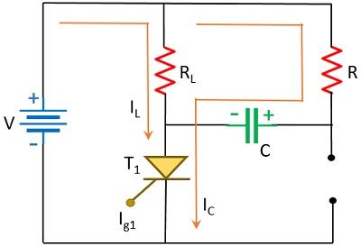
Mode I: In this mode of operation, the circuit is provided with dc supply input and along with that thyristor T1 is triggered with a gate signal. Due to this, T1 will come in conducting state. This leads to two currents one will be the load current while the other will be the charging current of the capacitor to flow through the whole circuit.

The load current and capacitor current are given as:
![]()
While the charging current will be:
![]()
Hence, the overall current that flows through SCR T1 will be the sum of load current and charging current. Thus, is given as:
![]()
Due to the flow of the charging current, the capacitor gets charged up to the peak of the supply input according to the polarity as shown in the above figure.
However, the charging current reduces to 0, once the capacitor gets fully charged up to the supply input, and thus the only current that continues to flow through T1 is the load current. Even when the moment C is holding the charge, T1 continues to remain in conducting state. Hence,
T1 = on; T2 = off; VC = V
Now, our attempt should be to commutate T1 and this is explained in the next mode of operation.
Mode II: In this state of operation, T2 is provided the gate pulse that triggers it and this leads to turning off T1. Now, the question arises, how this actually happens?
So, this mode of operation is such that by providing a triggering pulse to T2 the path becomes short-circuited. Once this happens, the polarity of the charge stored by the capacitor reverse biases the thyristor T1.

This reverse biased condition leads to turning off of the thyristor T1. So, when T2 is in conducting state,

The current flowing through R-T2 will be given as:
![]()
The load current flowing through RL-C-T2 charges the capacitor and its value will be given as:
![]()
: 2V corresponds to the summation of supply input and voltage existing across the capacitor.
However, the flow of current through the capacitor again charges the capacitor but this time with reverse polarity i.e., opposite to the case discussed previously.

Further, like the previously discussed case, the current flowing through the capacitor reduces to 0 once the capacitor gets charged fully.
Thus, the overall current flowing through thyristor T2,
![]()
So, by triggering T2 i.e., complementary SCR, the main SCR T1 will get turned off.
Hence, mode II operation provides,
T1 = off; T2 = on; VC1 = -V
Now, the next mode of operation of this commutation is based on turning on the main thyristor while turning off the auxiliary one.
Mode III: In order to turn off T2, T1 is triggered using gate pulse. Once T1 starts conduction then the polarity existing across C reverse biases T2 due to which T2 stops conduction and the current flows through T1 like we have discussed in mode I operation.

Hence, the mode III operation will lead cause
T1 = on; T2 = off; VC = V
Waveform Representation
The waveform representation of the class C commutation technique is given below:

Here Ig1 and Ig2 represent the gate triggering pulses applied to thyristors T1 and T2 respectively. VT1 and VT2 are the voltage drops across T1 and T2 respectively. The current flowing through T1 and T2 respectively are represented by IT1 and IT2. Also, VC and IC represent the voltage and current across the capacitor respectively.
Leave a Reply