Thyristor or SCR is an intricated semiconductor device and so its protection during operation is quite an important aspect that is needed to be dealt with. For thyristors, it is generally said that the device operates in an efficient manner when the operation takes place under specified ratings.
Here in this content, we will see in detail from which conditions thyristors are needed to be protected and the techniques adopted. But before that one must properly know the constructional feature of the thyristor and working of the thyristor.
Basics of Thyristor Protection
We have said in the beginning that the device must operate within limits. But what happens when the device exceeds the specified rating?
We all are aware of the fact that no device is ideal and on a practical basis, overvoltage or overcurrent conditions may get introduced during operation. Some of the conditions are:
- When SCR is turned on then di/dt can be quite large that cannot be handled by the device.
- A high value of dv/dt leads to cause the unexpected triggering of the device (i.e., without the presence of gate pulse).
- Sometimes the existence of an unwanted signal at the gate cathode terminal also triggers the device.
All the above-discussed conditions are not suitable for the reliable operation of thyristor thus it must be protected against such rare and dangerous conditions.
The various thyristor protection schemes are as follows:
- di/dt Protection
- dv/dt Protection
- Overvoltage Protection
- Overcurrent Protection
- Gate Protection
Let us now understand each one separately.
di/dt Protection
We know di/dt corresponds to the rate of change of current with time. In the forward biased state of thyristor, under the presence of a gate signal, the thyristor begins to conduct. Basically, in this condition, the flow of anode current takes place near the gate cathode junction of the device and further spreads out over the complete junction in a steady manner.
It is to be noted here that the design of the thyristor must be such that the current must rapidly reach out to the whole region.
In case, the rate with which the anode current is rising is comparatively higher than the spreading velocity of mobile carriers. Then high current density at the junction will lead to the generation of local hot spots near the gate region. The production of local hotspots leads to cause location-specific heating inside the device and this may destroy the thyristor. To deal with this, the di/dt must be within the specified limits when thyristor gets on.
Method to limit the current
The use of a small inductor that forms a series connection with the anode circuit helps in limiting the di/dt. The inductor helps in maintaining the di/dt up to the threshold value. We know that it is the property of the inductor to oppose the change in current.
So, suppose Vs is the voltage across the inductor,
Hence, the higher the value of inductance, the lower will be the rate of change of current.
As the main reason for damaging the thyristor is the formation of local hotspots thus, if the current gets rapidly spread out over all the region, then local hotspots will not get formed. To get this, the gate current must be applied with the value approximately around its maximum specified value but not more than that.
dv/dt Protection
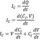
Due to the forward applied potential across the anode and cathode of the thyristor, the two external junctions get forward biased but the intermediate junction will be reverse biased. Because of the charges present within the depletion region near this junction, it acts as a capacitor, with junction capacitance Cj. If the applied anode to cathode voltage appears across the depletion region containing charge Q, then the charging current Ic will be given as:

The junction capacitance Cj is invariable thus, the value of dCj/dt will be zero. Hence,
![]()
From the above equation, it is clear that if the rate with which forward voltage is rising, affects the charging current Ic, as the two are directly proportional to each other. Here the charging current acts as gate current and turns on the SCR even in the absence of an actual gate pulse. As here the current is associated with the rate of change of applied potential thus, even a small change can turn the device on.
Method to deal with false triggering
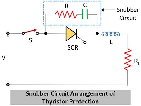
To deal with this, a snubber circuit is used. The figure below shows the snubber circuit, where a series combination of resistor and capacitor is connected in parallel with the SCR in the given configuration.

Here in this circuit capacitor can handle the false triggering quite well. When the switch S, in the circuit, is closed, then applied voltage appears across the circuit. The flowing current will be bypassed through the capacitor and the drop across the thyristor will be zero. By the time, the voltage will get build-up across the capacitor hence the specified dv/dt rating of SCR will be maintained. So, this will resultantly prevent the unexpected turning on of the device. But the question arises-
What is the need for a resistor over here in series with a capacitor?
From the above-discussed process, it is clear that the applied voltage charges the capacitor C. But when gate pulse is applied and SCR gets on then the capacitor starts discharging through the thyristor. As this will be a low resistance path, the excessive current may destroy the thyristor. To prevent this damage, the discharge current must be limited, and for the same resistance R of high-power rating, is placed in series with C.
Here the parameters must be properly selected as practically, they are adjusted to obtain the proper result.
Overvoltage Protection
Protection of thyristors from overvoltage is one of the major concerns. When these devices are subjected to high voltages, then there are chances of maloperation such as unusual turning on of the device or permanent damage because of reverse breakdown. In the case of thyristors, the overvoltage can be of two types:
- Internal Overvoltage: Sometimes a high internal voltage is generated when commutation of thyristors occurs. Even when anode current becomes zero, the stored charges reverse the anode current. Once the peak of this reverse recovery is attained the SCR starts blocking. After attaining the peak, the current further starts to decrease with possessing a large change in current.
The presence of large inductance within the circuit will produce a large transient voltage which is quite higher than the breakover voltage of the device and this may damage the device permanently. - External Overvoltage: External overvoltage is associated with the interrupt in the flow of current through the inductive circuit. Also, the lines that provide the supply to the thyristor when subjected to lighting leads to overvoltage. During the turn-on of the thyristor, large overvoltage appears across the load because of which a high amount of fault current flows. Such a high voltage damages the thyristor by causing inverse breakdown. Thus, must be avoided or suppressed to prevent damage.
Overcurrent Protection
SCRs possess low value of thermal time constants. Thus, the faulty conditions lead to overcurrent due to which the temperature at the junction becomes higher than the specified value. Thereby destroying the device. Hence, overcurrent protection is quite necessary. So, circuit breakers or fuses are required to resists the flow of current more than the rated value.
However, the type of system where the measures have to be applied is to be properly considered. For a weak supply network, the fault current is limited, by keeping the source impedance below the surge current rating of the SCR. This means conventional fuses and circuit breakers are employed to deal with overcurrent.
It is to be noted here that the operation must occur in a coordinated way by ensuring that before the overcurrent could damage the device, it must be controlled and the branches that are faulty must be isolated.
Gate Protection
Protection of the gate circuit from overvoltage and overcurrent is quite an important aspect when we deal with thyristor protection. We have already discussed that when overvoltage exists then it leads to false triggering of the thyristor. While due to overcurrent, the junction temperature may rise by which the device gets damaged.
Besides this, spurious signals appear at the gate terminal when there exist transients in the power circuit. Due to this, the SCR gets on by the unwanted gate triggering. Thus, in order to protect the gate terminal from such actions, shielded cables are used for gate protection. The presence of such cables lowers the chances of inducing emf thus, the unwanted triggering of the thyristors is minimized to large extent.

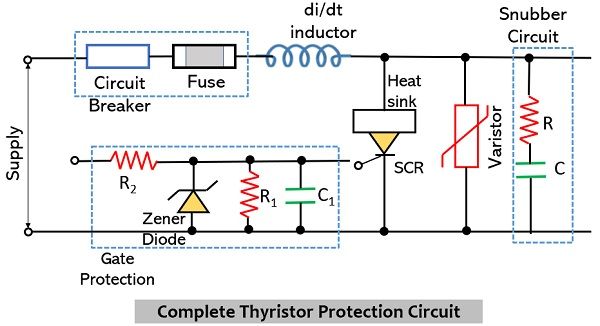
Hence, the complete thyristor protection circuit with all the above-discussed measures is shown above.
Leave a Reply