Class B commutation of thyristor is another type of forced commutation technique that is used to turn off the SCR. In this commutation technique, the device gets turned off by building reverse current in a gradual manner from cathode to anode. Thus, is also referred to as current commutation or resonant pulse commutation.
It is a forced type of self-commutation of SCR that makes use of resonating LC circuits.
Basics of Commutation of Thyristor
Previously we have discussed that unlike the turn-off process of thyristor, the turn-off is not associated with any gate triggering pulse. And once the device gets turned on then even after the removal of the gate triggering pulse, the SCR remains in on state. So, some techniques must be implemented to turn the device off.
This involves two methods; one is current commutation where the anode current of the circuit is reduced below the holding current. While the other is voltage commutation where the anode terminal is kept at low potential than the cathode terminal i.e., applying reverse-biased voltage.
Either of the methods is to be applied for a definite period of time to turn the device off. In our last content, we have discussed class A commutation which is the first type of forced commutation. Let us have a brief idea about the same.
Class A Commutation
In this commutation technique, a combination of inductor and capacitor is considered which acts as commutating components that turn the SCR off. These are present at load thus is also regarded as load commutation.
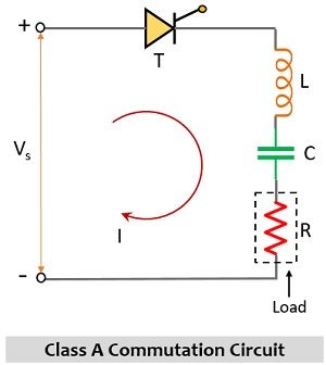
In class A commutation, the device gets turned off when the current naturally attains 0 value because of the presence of an inductor in the circuit which holds the property of opposing the change in current. Thus, the output current will starts decreasing and a point will reach where the current attains zero value then this turns the SCR off, and simultaneously, the capacitor in the circuit discharges. With the discharge of the capacitor, the drop across the SCR starts increasing.
Circuit of Class B Commutation
The figure below represents the circuit of class B commutation:
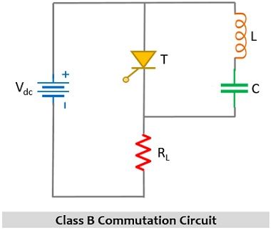
From this figure, we can clearly differentiate that the above-given circuit is different from the circuit of the class A commutation technique. Here LC resonant circuit is in parallel connection across the SCR but is not serially connected with the load like in class A commutation. Thus, here the load current does not pass through the commutating components i.e., L and C.
Now, just like the class A commutation, there are also necessary conditions associated with class B commutation, so the question arises what are these necessary conditions that are required to be fulfilled.
- The commutating components LC and should be resonating in nature.
- Initially, the capacitor in the circuit must be charged by Vdc.
- The load current must be constant.
Let us now proceed to understand how the operation of the class B commutation circuit takes place.
Working of Class B Commutation
It is clearly shown in the circuit representation that the commutating components are not in series with the load.

At the initial level when external input supply Vdc is provided to the circuit then this causes the capacitor to get charged. As no gate excitation is provided to the SCR thus the externally supplied input signal will not bring the thyristor into the forward conduction mode. But due to the supply input, the current in the circuit flows through commutating components L and C and the load, this is shown below:
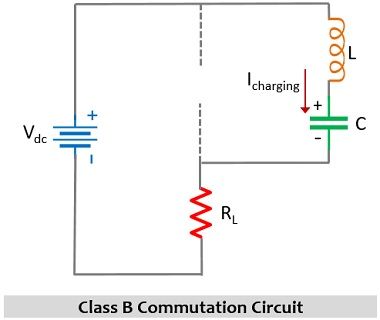
This causes charging of the capacitor with the same polarity as that of the supply input. The capacitor gets charged up to the peak of supply input voltage. As the capacitor does not have a path to discharge thus it will hold the charge +Vdc.
Moreover, at this time, if the thyristor is triggered, then the device comes in forward conduction mode. And so in this condition, SCR starts conduction and current begins to flow from the thyristor and load (i.e., RL) part of the circuit. However, once T gets on then there will short circuit and this time the capacitor will get the path from where discharging will take place. The direction in which current flow through the thyristor takes place is shown below:
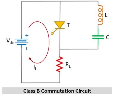
Now, once the capacitor gets completely discharged then due to the direction of flow of discharging current, reverse polarity will exist at the capacitor. More simply, in the presence of supply input and gate triggering pulse, the thyristor will be in on state and at the same time after getting discharged once, the capacitor begins to charge with opposite polarity.
The reverse potential at the capacitor will cause the current to flow in the reverse direction to that of the load current as shown below:
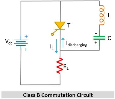
This current is known as commutating current and is denoted by IC and this IC opposes the flow of IL in the given circuit. As soon as the value of IC exceeds IL then this makes the current flowing through the thyristor (ISCR) fall below the value of holding current resultantly turning the thyristor off.
Hence, in this way, the commutation of thyristor takes place. However, once the thyristor gets turned off, then the capacitor begins to charge with its original polarity through the inductor and the load part of the circuit, and after getting fully charged, like the way we have discussed above the thyristor will come into the conducting state.
From this discussion, we can conclude that the device gets on and off for some period of time and this is a continuous process. However, the turn-on and turn-off frequency of the device depends on the value of commutating components i.e., L and C because charging and discharging of capacitor plays a crucial role in the same.
Waveform for Class B Commutation
The figure below represents the waveform representation of the class B commutation circuit:
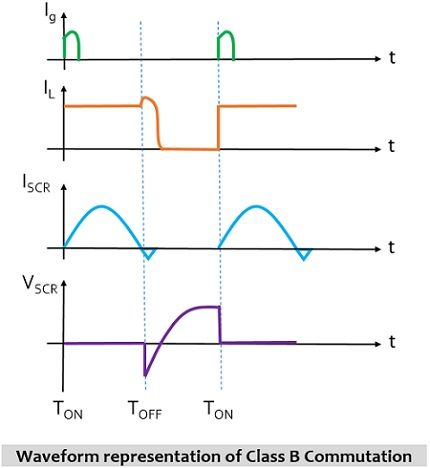
Here, Ig corresponds to gate triggering pulse, IL is the load current, ISCR is the current flowing through the thyristor and VSCR denotes the drop across the thyristor.
We have already considered one of the assumptions that the load current is constant. Thus, before providing the gate pulse, the SCR is charged up to the peak of the supply unit and once the gate triggering pulse is provided then a constant load current flows through the circuit and simultaneously current begins to flow through the SCR. Due to the discharging current of the capacitor, the load current decreases and gradually will reach 0.
However, after a point of time, the thyristor will stop further conduction and gets commutated. And as we have mentioned while discussing the working that it is a continuous process that gets repeated after some time duration thus, in this way the operation continues.
It is to be noted here that when the SCR is in conducting state then the drop across the thyristor will be 0. And the voltage drop increases when the thyristor moves from conducting to a non-conducting state.
In most cases, this commutation technique shows usefulness in chopper circuits.
Leave a Reply