Class A commutation of thyristor is a type of forced commutation and is also referred to as Load Commutation. It is one of the widely used commutation techniques that mainly find applications in high-frequency operations.
Previously we have discussed that commutation of thyristor corresponds to turning the SCR off. Let us have a brief idea about-
Commutation Techniques of Thyristor
We have discussed thyristors that even after being in forward biased condition, the thyristor does not conduct until and unless gate pulse is not applied to it. So, a gate pulse is necessarily required to trigger the SCR. But there are some questions like, what about turning the device off, is it will be done automatically or we need to add some external circuitry to commutate the device.
So, we have already seen previously that there are majorly two types of commutation techniques, natural and forced.
Class A commutation is a sub-classification of forced commutation sometimes called self or resonant commutation. To commutate the thyristor, two necessary actions must be considered:
- IA > IH i.e., anode current must be less than holding current.
- The potential at anode must be lower than the cathode.
Circuit of Class A Commutation
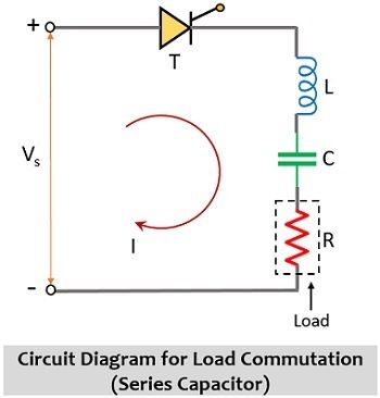
The circuit representation for load commutation is shown below:

In the circuit given below it is clearly shown that load i.e., R is connected serially with the commutating components i.e., L and C. Generally, when values of R, L, and C are low then in that case, the elements are arranged serially along with SCR as shown above.
On the contrary when the load resistor possesses a high value then it is connected in parallel across the capacitor while this parallel combination is connected in series with the inductor. The figure below shows the shunt capacitor circuit of load commutation:

It is to be noted here that the necessary condition that both the above circuits should fulfill is that they must be underdamped circuits of second order. These circuits are excited with dc input.
Working of Class A Commutation
On applying an external dc input signal, the current starts flowing through the circuit. In order to turn on the SCR in the circuit, a gate trigger pulse is required. So, simultaneously gate signal is applied that will put the thyristor in forward conduction mode. We have already discussed the same that gate pulse is necessarily required to turn on the SCR. Hence, after the SCR gets on, the forward current that flows through the SCR begins to charge the capacitor. At the same time, the inductor connected in the circuit stores energy.
We know that it is the property of the inductor, that it opposes the change in current. So, once the capacitor gets charged up to the peak of the supply input, the polarity of the inductor connected in the circuit will get reversed and now the inductor will oppose any further flow of current through it. As the inductor does not further allow the flow of current, the output current starts to decrease and reaches zero.
This means here the commutating components make the current through the load zero and this commutate the thyristor. This signifies that unlike the turning on of the SCR where the gate terminal acts as a direct switch to turn the device on, in the turn off no direct switch exists and so with the use of external components, the device is commutated.
The above-explained circuit working shows that naturally the current decays to zero and the reason is the respective commutating components. And as load components are responsible to turn the thyristor off thus are given the name load commutation.
Necessary Condition:
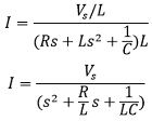
We have already discussed in the beginning that to achieve load commutation, the circuit must be underdamped. We know that the current flowing through the circuit is given as:

Further, writing the above equation in Laplace transform,
![]()
: R + Ls + 1/sC = Z that corresponds to the overall impedance of the circuit due to serially connected elements.
On rearranging,

On simplifying,
The characteristics equation for the above equation is given as:
![]()
However, the standard characteristics equation is given as:
![]()
: ξ corresponds to the damping ratio and
ωn denotes the natural angular frequency
On comparing the above two equations, we will get,

Here,
![]()
For underdamped system, ξ < 1

This is the condition for an underdamped system.
The resonant frequency is given as:
![]()
The maximum conduction time of SCR is given as:

For α as firing angle,
![]()
Waveform for Load Commutation
The figure below shows the waveform representation:

In the above representation, it is clearly represented that after providing gate pulse, the SCR gets on. In the on state of SCR, the capacitor will charge and the voltage across the capacitor reaches the peak of supply input and simultaneously current flows through the circuit. In the on state of SCR, the drop across SCR will be 0.
We have discussed that after the capacitor gets charged up to supply voltage, the inductor releases its stored energy and opposes the further flow of current. The energy released by the inductor, further, energizes the capacitor and this is shown in the above waveform that the voltage across the capacitor increases beyond the supply input. By this time, the current that flows through the circuit decays as the inductor starts opposing it and a time will reach when the current becomes 0 then SCR will automatically turn off and this is shown in the above figure.
At this instant, now the capacitor starts to discharge, and as the SCR gets turned off so the drop across the SCR will start increasing.
Leave a Reply