A sub-classification of forced commutation technique in which the main thyristor is commutated by application of reverse voltage along with the use of an auxiliary thyristor is known as Class D Commutation of Thyristor. As it uses reverse-biased voltage to turn the thyristor off it is also referred to as Voltage Commutation.
Sometimes it is called parallel capacitor commutation and the reason for this is that here when the auxiliary thyristor is turned on then to turn off the main thyristor, C gets connected across it.
What is the Commutation of Thyristor?
Commutating corresponds to turning the device off using external means. In the case of thyristor, we have already discussed previously that to turn the thyristors off either we perform voltage commutation or current commutation.
A thyristor gets on only when along with supply input, it is also provided with a gate triggering pulse. And once getting on, it remains in the conducting state, till the time it is made to come in off state using external techniques. The various techniques applied to turn the thyristor off lead to the classification of thyristor commutation techniques. Out of the two ways of commutation, in current commutation, anode current is reduced below holding current to commutate the device while, in voltage commutation, reverse-biased voltage is applied across the anode-cathode terminal of the device.
Circuit of Class D Commutation
The figure given below shows the circuit representation of class D commutation of thyristor:
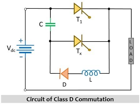
Here, T1 is the main thyristor that is required to be commutated while Tx is an auxiliary thyristor which is part of external circuitry that turns off the device. However, the circuit also includes elements such as a capacitor, diode, and inductor combinedly that operate to perform the commutation of the thyristor. We have already mentioned that it is a type of forced commutation and we know that in forced commutation dc input supply is required thus the external source of supply here is dc signal Vdc.
In the above figure, the main thyristor T1 and the load L constitute the power circuit. Whereas auxiliary thyristor Tx, diode, and inductor form the commutation circuit.
Like the previously discussed classes of thyristor commutation, here also the necessary assumptions are as follows:
- The load current must be constant.
- The capacitor is charged up to the maximal value of the supply input.
In this commutating circuit, according to the voltage polarity, the main thyristor gets turned off.
Working of Class D Commutation of Thyristor
To understand how the operation of the whole circuit takes place, consider the circuit representation shown above.

Initially, on applying voltage V across the circuit but in the absence of gate triggering pulse both the thyristors are in the off state. Due to the supply input, the diode in the below-given figure is in reverse biased condition thus, no flow of current takes place through the circuit hence the voltage across the capacitor will be 0.
Further, out of the two thyristors, the auxiliary thyristor is provided gate triggering pulse which brings it to conducting state. Thus, the current starts to flow in the circuit as shown below:
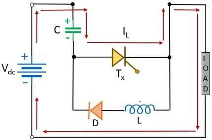
This flow of current charges the capacitor C with a similar polarity as that of supply input and it gets charged up to the peak of the supply value i.e., Vdc. While the current flows from the positive terminal of the battery to the negative terminal by passing through the load. However, once the capacitor gets fully charged then the polarity across the capacitor reverse biases the auxiliary thyristor i.e., Tx leading to turn it off. Hence, in this case, the capacitor will store the charge.
Moreover, once Tx gets turned off then gate triggering pulse is given to thyristor T1 thus it will get turned on under the presence of supply input. As T1 comes into the conducting state, then there will be two loop currents that will flow through the circuit, and the flow of currents through the circuit is clearly shown below:
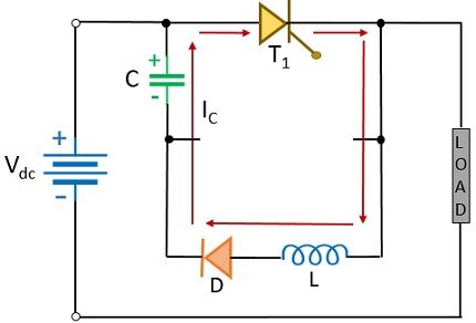
The current IL corresponds to the load current and we have already assumed it to be constant at the beginning itself. While IC corresponds to the current flowing through the series LC circuit which gives rise to LC oscillations within that loop. This current will be the discharging current of the capacitor.
As the negative half of the signal will reverse biases the diode, therefore, that part of the circuit will be in conducting state only during the positive half of the signal. In this case, the inductor will store the energy, but as it is the property of the inductor that it opposes the current that produced it hence the inductor starts releasing the stored energy.
Due to the release of the stored energy of the inductor, the capacitor in the circuit gets charged again but this time with opposite polarity than the former case. Thus, the loop current flowing through that part of the circuit will be:
![]()
Now, as T1 is in conducting state and we have to commutate T1 thus, for this we need to trigger Tx i.e., the auxiliary thyristor. Once, Tx begins to conduct along with T1 then the polarity across the capacitor will bring T1 to a reverse-biased state and this will lead to turning the thyristor off, this is clearly represented below:
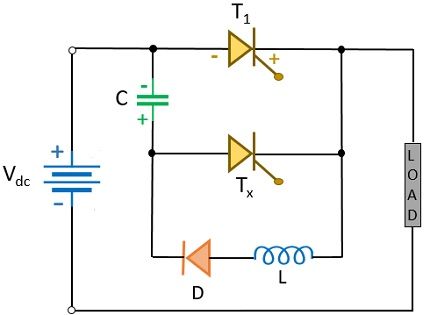
Thus, once T1 gets turned off then the current through the circuit will flow in the manner as shown below:
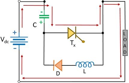
And this current will continue to flow till the time the capacitor is holding the charge of reverse polarity as the supply input.
Waveform Representation
The figure given here represents the waveform representation of the class D commutation technique:
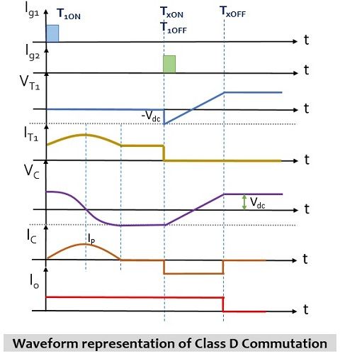
At the time when Tx is turned on, then T1 is in off state and C gets charged up to the maximum of supply input. In this case capacitor and auxiliary thyristors are carrying the load current. As the capacitor is getting charged with constant load current thus, there is a linear rise in voltage across the capacitor.
When T1 is triggered then the voltage across the capacitor turns the auxiliary thyristor off and to turn off the main thyristor, Tx is triggered again. The turn-off time of the main thyristor is represented as tc.
ayyan says
thanks for provide this notes