Binary Number System comprises of two digits 0 & 1, thus, the base of the binary number system is 2. Thus, it is called as a base-2 system. It is much easier and simpler than decimal number system because it is comprised of only two digits.
In binary number system, any number can be expressed by array of numbers in which each coefficient is calculated by successive power of 2. The representation of decimal numbers is done by expressing the digits of the number in power of 10. Similarly in binary numbers the digits of each number is expressed in power of 2.
This is clearly shown below:
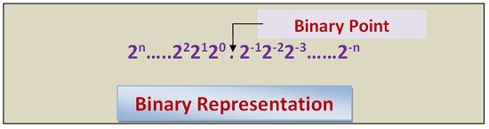
Positional Value of Binary Digits
The positional value of binary digits in increasing positive numbers when moving to left side from binary point or decimal. When we move rightwards from binary point or decimal point the power will increase but on negative real scale.
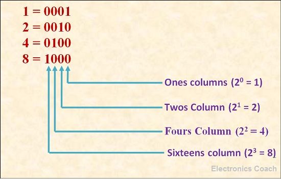
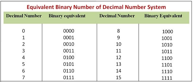
Counting in Binary Number system
We count from 0 to 9 in decimal number, similarly we can count in binary number. Consider a number 2 in decimal. To convert this number into binary we need to start count from 20, which is equal to one. But we need 2. Thus, the successive number in counting will be 21, it is equal to 2, thus the binary equivalent of 2 is 0010, we have to place 1 when power raised to 2 is considered.
When the 2 raised to positional number is not considered than we will write 0 on that place.
Terminology associated with Binary Number System
- Bit: Each binary digit in binary number system is called as Bits. Bits is formed by merging two words binary and digits.
- Byte: In digital systems, group of eight bits is called nibble.
- Nibble: The group of 4 bits is called nibble.
Applications of Binary Number System
- Digital Computers: Digital computer have significant involvement of binary number. This is because in digital systems, there are only two states either “ON” or “OFF”. Binary Numbers also has two symbols for representation.
- Transistor: Transitor is also one of the type of two stage devices, thus binary numbers can be used to represent its states.
- Punched cards: In punched card there are two states, one with punching and other without punching, thus binary numbers can represent its states too.
- Magnetic cores in digital computers: When current flow in wire, magnetic field is created around it thus, magnetic field is created either in clockwise direction or in anticlockwise direction.
Conversion to binary Number System
From Decimal to Binary Number System: Divide the given decimal number by 2 and write the remainder next to each quotient. Continue this process till you get 0 as quotient. Now, the last reminder will be the MSB (Most Significant Bit) and the first reminder will be LSB (Least Significant Bit). Write the binary digits in reverse order i.e. from MSB to LSB.
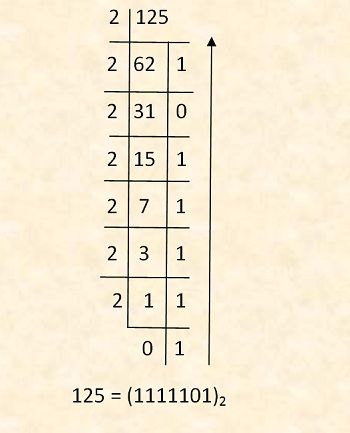
The result is the required binary digits. Thus, the given decimal number is converted into binary number.
Adnan Anam says
A very useful post for a quick recap
Doreen says
This is excellent. Thank you