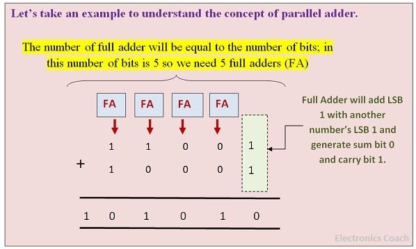
Definition: The Parallel binary adder is a combinational circuit consists of various full adders in parallel structure so that when more than 1-bit numbers are to be added, then there can be full adder for every column for the addition. The number of full adders in a parallel binary adder depends on the number of bits present in the number for the addition. If 4-bits numbers are to be added, then there will be 4-full adder in the parallel binary adder.
The parallel binary adder can be designed with the help of basic logic gates. The sub-modules in the logic circuit will resemble the logic circuit of half adder and full adder. To understand it clearly let’s put light on designing and working of the 2-bit parallel binary adder.
Logic circuit of 2-Bit Parallel Binary Adder
The 2-Bit parallel adder can be designed with the help of EX-OR (Exclusive OR) gate and AND gate. If you will carefully observe the logic circuit of 2-Bit Parallel Binary Adder, you will notice 2-full adder are connected in a parallel manner. Now, you can easily guess how this will work.

We have discussed in our article of difference between the half adder and full adder, that half adder is a logic circuit which adds two 1-bit numbers but does not add carry from previous addition. Therefore, full adders came into existence. A full adder can add two 1-bit numbers along with the carry from previous addition.
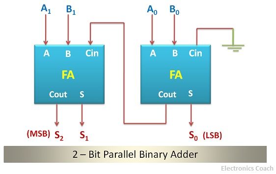
Now, coming back to the parallel binary adder, it also has two full adders. When we start addition of two numbers, the first step we follow is the addition of LSB (Least Significant Bits) of two numbers. After this, if we have any carry we forward it to higher order columns. Now, the adder performs the similar task; it adds the LSBs of both the numbers and if any carry bit is there it passes it to the carry-in terminal of another.
You may use half adder for the addition of LSBs of both the numbers as for the addition of LSBs there is no previous carry from previous addition. But for the addition of bits present in higher order column, you must use full adder because there may be or may not be a carry from previous addition.
5-Bit Parallel Binary Adder
We have completed discussion about 2-bit parallel binary adder; now you must be knowing that if we have two numbers with 5-bits than what we need. We will definitely use 5-bit parallel binary adder for performing this task.
Let’s focus on the block diagram of the 5-bit parallel binary adder. It consists of 5-full adders, each of the 5-full adders have 3-input terminals and 2-output terminals. The 2-input terminals are available for entering two numbers to be added and one input terminal is used for entering the previous carry.
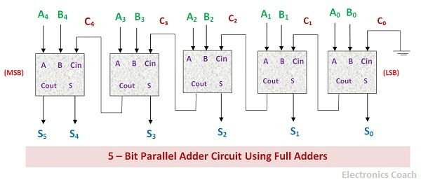
The carry generated from the addition will be generated from Cout terminal. The sum of the addition will be generated from the sum bit of the adder. It must be noted here that Cout stands for Carry-out and Cin stands for Carry-in. The connection will be such that the Cout terminal of a full adder will be connected to the Cin terminal of next full adder used for higher order column.
For addition of LSBs, we have a choice of either to use half adder or to use full adder. This is because we don’t have the previous carry so half adder can also be used. If we wish to use full adder, then Cin terminal of the full adder can be grounded.
For other full adders connected to higher order column, this will not be a major issue. This is because the Cout terminal of the previous adder can be connected to the Carry-in of adders connected to higher order columns.
Significance of Parallel Binary Adder
With the help of full adder, we cannot add numbers of more than 1-bit. As the number of bits increases in a number, the columns of addition also increase. A full adder can add only one column; thus for every column, we need a full adder. This combined design of all full adder results in a combinational circuit which is called parallel binary adder.

One may think that why not a full adder stores the result of one operation of addition and then perform another addition. Let me tell you, do not get confused between the combinational circuit and sequential circuit. One of the most important facts about adder is that it is a combinational circuit. And a combinational circuit is one which does not have any memory storage element.
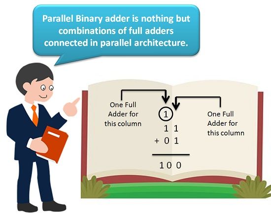
Therefore, for every column, we need a separate full adder. And thus, it becomes so-called parallel binary adder.
Advantages and Disadvantages of Parallel Binary Adders
The advantage of using Parallel binary adder is its fast processing. It is certainly beneficial for the addition of numbers with more than 1-bit. Apart from this during the addition process the all the bits are fed to the input terminals of adder simultaneously.
Now, You can easily compare this process with conventional addition process which we do with pen and paper. But in that we add one column at a time and in this several columns can be added simultaneously. Now you can estimate the speed of addition with the help of parallel binary adder; it is extremely fast.
Everything comes with pros and cons. Thus, parallel adders also have its own pros and cons, but the former outweighs the latter. If parallel connected full adders can increase the speed of operation, then these parallel-connected adders are also responsible for the increased complexity of the circuit. The higher the number of bits the more will be the circuit complexity.
Pascal says
Very nice indeed!