Definition: Boost Converters sometimes, also known as step-up choppers are the type of chopper circuits that provides such an output voltage that is more than the supplied input voltage. In the case of boost converters, the dc to dc conversion takes place in a way that the circuit provides a high magnitude of output voltage than the magnitude of the supply input.
It is given the name ‘boost’ because the obtained output voltage is higher than the input voltage.
Introduction
We have already mentioned in the beginning that boost converters are types of chopper circuits. In chopper circuits, we have discussed that it performs dc to dc conversion, i.e., a fixed dc voltage is changed into an adjustable dc voltage.
Previously, we have seen another type of chopper circuit i.e., buck converter. Buck converters generate an output voltage that is lower than the supplied input. So, we can say, boost converters are the ones that perform a reverse operation of the buck converter. Due to the type of operation performed by boost converters, these are referred to as step-up choppers.
It is to be noted here that since the product of voltage and current results in power then with the increase in the output voltage, the output current through the circuit will automatically decrease.
In chopper circuits, power MOSET, BJT, IGBT, etc. are used as switches while the thyristors are not used for such purposes and the reason for the same is that an external commutation circuit is needed in order to commutate the device.
Operating Principle of Boost Converter
The figure given below is the circuit representation of the boost converter:
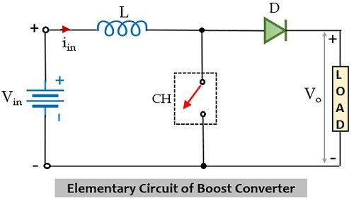
The circuit here is an elementary form of step-up chopper which necessarily requires a large inductor L in series connection with the voltage source. The whole circuit arrangement operates in a way that it helps in maintaining a regulated dc signal at the output.
Let us understand how the given circuit operates in order to provide an increased dc signal at the load.
Initially, when the chopper CH is in on state, then in the presence of supply dc input current begins to flow through the closed path of the circuit i.e., passing through the inductor as shown in the figure below.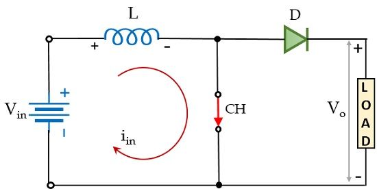
Here, the polarity of the inductor will be according to the direction of the flow of current. In this particular case, the diode in the configuration is in reverse biased condition and so current will not be allowed to flow through that particular part of the circuit during on state of the chopper. Resultantly, the voltage across the chopper will appear across the load.
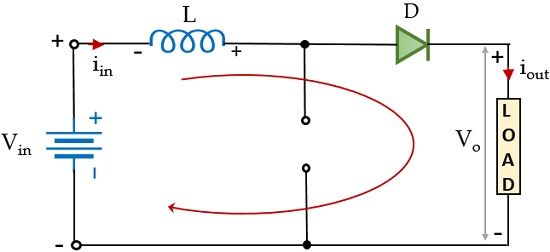
Furthermore, at the instant when CH is in the off state, then the part of the circuit through which the current was flowing earlier will not be active in this case. However, as the inductor stores, the energy in the form of a magnetic field and so the current through it will not die out instantly.
Also, we know according to Lenz’s law a reverse current will be induced that will oppose the cause which has produced it. And so, due to the induced current, the polarity of the inductor will get reversed. This reverse polarity of the inductor forward biases the diode present in the circuit. This provides the path for the current through the diode that flows through the load during the off state of the chopper i.e., Toff. However, we must note here that the current through the inductor is of decreasing nature and will die out after a point in time.
Thus, the total voltage across the load will be given as:
![]()
This means that the output voltage exceeds the applied input voltage. Thus, performs step-up conversion as the energy stored within the inductor during the Ton period is released during the Toff period.
During the Ton period, the voltage across the inductor will be given as:

Let us have a look at the waveform representation of the step-up chopper shown below:
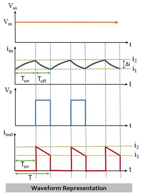
During the Ton period, the current through the inductor will change from i1 to i2 this is clearly shown above. While during the Toff period, the inductor current will change from i2 to i1. Now, talking about voltage, so during the turn-on period, the voltage across the inductor will be equal to the supply input voltage. But when CH gets off then on applying KVL in the figure shown above, we will get,
![]()
This means,
![]()
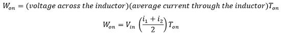
Considering that output current is varying linearly, the energy input provided by the source to the inductor, when CH is on, is given as:
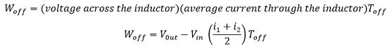
Further, the energy that the inductor releases to the load when CH is off is given as:
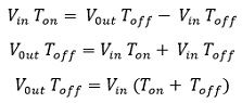
For a lossless system, comparing the two energies, we will have,
![]()
On simplifying,
Since we know, T = Ton + Toff, therefore,
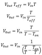
Since, we know, duty cycle i.e., α = Ton/ T
![]()
Thus, we can conclude here that the average load voltage can be stepped up with the change in the duty cycle.
Applications
Due to the operating principle of step-up choppers, these find applications in the regenerative braking of dc motors. Along with this, these are used in various consumer electronics, battery power systems, power amplifier circuits, power factor correction circuits, automotive equipment, etc.
Leave a Reply